Transaction Level Modeling, is a modeling style for building highly abstract models of components and systems. In this scheme, data is represented as transactions (class objects that contain random, protocol specific information) which flow in and out of different components via special ports called TLM interfaces. This brings about a higher level of abstraction which is very much required in today's verification environments because of the large amount of signals associated with different protocols. It would be a lot simpler to understand, debug and verify if we can represent data and changes in signals as transactions (like write operation/read operation).
UVM provides a set of transaction-level communication interfaces that can be used to connect between components such that data packets can be transferred between them. The good part about this setup is that it isolates a component from the changes in other components, and promotes reusability and flexibility because now you can just swap a component with another which also have a TLM interface.
class simple_packet extends uvm_object;
	`uvm_object_utils (simple_packet)

	rand bit [7:0] addr;
	rand bit [7:0] data;
		 bit 		rwb;

	constraint c_addr { addr > 8'h2a; };
	constraint c_data { data inside {[8'h14:8'he9]};

endclass
simple_packet class object will be a transaction that can be sent from componentA to componentB via TLM interface ports port and export.

A forever loop runs forever, or for infinite time.
Syntax
	forever
		// Single statement

	forever begin
		// Multiple statements
	end
A forever loop is similar to the code shown below in Verilog. Both run for infinite simulation time, and is important to have a delay element inside them.
An always or forever block without a delay element will hang in simulation !
	always
		// Single statement

	always begin
		// Multiple statements
	end
In SystemVerilog, an always block cannot be placed inside classes and other SystemVerilog procedural blocks. Instead we can use a forever loop to achieve the same effect.
The pseudo code shown below mimics the functionality of a monitor in testbench that is once started and allowed to run as long as there is activity on the bus it monitors.
class Monitor;
	virtual task run();
		forever begin
			@(posedge vif.clk);
			if (vif.write & vif.sel)
				// Capture write data
			if (!vif.write & vif.sel)
				// Capture read data
		end
	endtask
endclass

module tb;
	Monitor mon;

	// Start the monitor task and allow it to continue as
	// long as there is activity on the bus
	initial begin
		fork
			mon.run();
		join_none
	end
endmodule
Most digital designs are done at a higher level of abstraction like RTL, although at times it becomes intuitive to build smaller deterministic circuits at a lower level by using combinational elements like and and or. Modeling done at this level is usually called gate level modeling as it involves gates and has a one to one relation between a hardware schematic and the Verilog code.
Verilog supports a few basic logic gates known as primitives as they can be instantiated like modules since they are already predefined. Other complex behavior can be defined under Verilog User Defined Primitives.
| Gate Types | Syntax | Description |
|---|---|---|
| and | and u0(out, i1, i2, …) | Performs AND operation on two or more inputs |
| or | or u0(out, i1, i2, …) | Performs OR operation on two or more inputs |
| xor | xor u0(out, i1, i2, …) | Performs XOR operation on two or more inputs |
| nand | nand u0(out, i1, i2, …) | Performs NAND operation on two or more inputs |
| nor | nor u0(out, i1, i2, …) | Performs NOR operation on two or more inputs |
| xnor | xnor u0(out, i1, i2, …) | Performs XNOR operation on two or more inputs |
| buf | buf u0(out, in) | The buffer (buf) passes input to the output as it is. It has only one scalar input and one or more scalar outputs. |
| not | not u0(out, in) | The not passes input to the output as an inverted version. It has only one scalar input and one or more scalar outputs. |
| bufif1 | bufif1 u0(out, in, control) | It is the same as buf with additional control over the buf gate and drives input signal only when a control signal is 1. |
| notif1 | notif1 u0(out, in, control) | It is the same as not having additional control over the not gate and drives input signal only when a control signal is 1. |
| bufif0 | bufif0 u0(out, in, control) | It is the same as buf with additional inverted control over the buf gate and drives input signal only when a control signal is 0 |
| notif0 | notif0 u0(out, in, control) | It is the same as not with additional inverted control over the not gate and drives input signal only when a control signal is 0. |
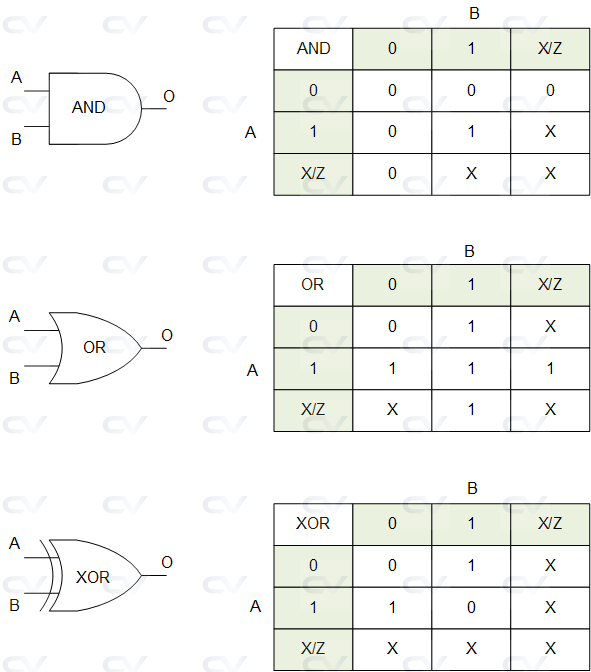
And/Or/Xor Gates
These primitives implement an AND and an OR gate which takes many scalar inputs and provide a single scalar output. The first terminal in the list of arguments to these primitives is the output which gets updated whenever any of the inputs change.
module gates (	input a, b,
				output c, d, e);

	and (c, a, b); 	// c is the output, a and b are inputs
	or  (d, a, b);	// d is the output, a and b are inputs
	xor (e, a, b); 	// e is the output, a and b are inputs
endmodule
module tb;
	reg a, b;
	wire c, d, e;
	integer i;

	gates u0 ( .a(a), .b(b), .c(c), .d(d), .e(e));

	initial begin
		{a, b} = 0;

      $monitor ("[T=%0t a=%0b b=%0b c(and)=%0b d(or)=%0b e(xor)=%0b", $time, a, b, c, d, e);

		for (i = 0; i < 10; i = i+1) begin
			#1 	a <= $random;
				b <= $random;
		end
	end
endmodule
ncsim> run
[T=0 a=0 b=0 c(and)=0 d(or)=0 e(xor)=0
[T=1 a=0 b=1 c(and)=0 d(or)=1 e(xor)=1
[T=2 a=1 b=1 c(and)=1 d(or)=1 e(xor)=0
[T=4 a=1 b=0 c(and)=0 d(or)=1 e(xor)=1
[T=5 a=1 b=1 c(and)=1 d(or)=1 e(xor)=0
[T=6 a=0 b=1 c(and)=0 d(or)=1 e(xor)=1
[T=7 a=1 b=0 c(and)=0 d(or)=1 e(xor)=1
[T=10 a=1 b=1 c(and)=1 d(or)=1 e(xor)=0
ncsim: *W,RNQUIE: Simulation is complete.
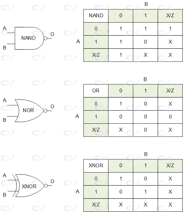
Nand/Nor/Xnor Gates
The inverse of all the above gates are also available in the forms of nand, nor and xnor. The same design from above is reused with the exception that the primitives are switched with their inverse versions.
module gates (	input a, b,
				output c, d, e);

	// Use nand, nor, xnor instead of and, or and xor
	// in this example
	nand (c, a, b); 	// c is the output, a and b are inputs
	nor  (d, a, b);		// d is the output, a and b are inputs
	xnor (e, a, b); 	// e is the output, a and b are inputs
endmodule
module tb;
	reg a, b;
	wire c, d, e;
	integer i;

	gates u0 ( .a(a), .b(b), .c(c), .d(d), .e(e));

	initial begin
		{a, b} = 0;

      $monitor ("[T=%0t a=%0b b=%0b c(nand)=%0b d(nor)=%0b e(xnor)=%0b", $time, a, b, c, d, e);

		for (i = 0; i < 10; i = i+1) begin
			#1 	a <= $random;
				b <= $random;
		end
	end
endmodule
ncsim> run
[T=0 a=0 b=0 c(nand)=1 d(nor)=1 e(xnor)=1
[T=1 a=0 b=1 c(nand)=1 d(nor)=0 e(xnor)=0
[T=2 a=1 b=1 c(nand)=0 d(nor)=0 e(xnor)=1
[T=4 a=1 b=0 c(nand)=1 d(nor)=0 e(xnor)=0
[T=5 a=1 b=1 c(nand)=0 d(nor)=0 e(xnor)=1
[T=6 a=0 b=1 c(nand)=1 d(nor)=0 e(xnor)=0
[T=7 a=1 b=0 c(nand)=1 d(nor)=0 e(xnor)=0
[T=10 a=1 b=1 c(nand)=0 d(nor)=0 e(xnor)=1
ncsim: *W,RNQUIE: Simulation is complete.
These gates can have more than two inputs.
module gates (	input a, b, c, d,
				output x, y, z);

  and (x, a, b, c, d); 	// x is the output, a, b, c, d are inputs
  or  (y, a, b, c, d);	// y is the output, a, b, c, d are inputs
  nor (z, a, b, c, d); 	// z is the output, a, b, c, d are inputs
endmodule
module tb;
	reg a, b, c, d;
	wire x, y, z;
	integer i;

  gates u0 ( .a(a), .b(b), .c(c), .d(d), .x(x), .y(y), .z(z));

	initial begin
      {a, b, c, d} = 0;

      $monitor ("[T=%0t a=%0b b=%0b c=%0b d=%0b x=%0b y=%0b x=%0b", $time, a, b, c, d, x, y, z);

		for (i = 0; i < 10; i = i+1) begin
			#1 	a <= $random;
				b <= $random;
          		c <= $random;
          		d <= $random;

		end
	end
endmodule
ncsim> run
[T=0 a=0 b=0 c=0 d=0 x=0 y=0 x=1
[T=1 a=0 b=1 c=1 d=1 x=0 y=1 x=0
[T=2 a=1 b=1 c=1 d=0 x=0 y=1 x=0
[T=3 a=1 b=1 c=0 d=1 x=0 y=1 x=0
[T=4 a=1 b=0 c=1 d=0 x=0 y=1 x=0
[T=5 a=1 b=0 c=1 d=1 x=0 y=1 x=0
[T=6 a=0 b=1 c=0 d=0 x=0 y=1 x=0
[T=7 a=0 b=1 c=0 d=1 x=0 y=1 x=0
[T=8 a=1 b=1 c=1 d=0 x=0 y=1 x=0
[T=9 a=0 b=0 c=0 d=1 x=0 y=1 x=0
[T=10 a=0 b=1 c=1 d=1 x=0 y=1 x=0
ncsim: *W,RNQUIE: Simulation is complete.
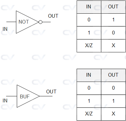
Buf/Not Gates
These gates have only one scalar input and one or more outputs. buf stands for a buffer and simply transfer the value from input to the output without any change in polarity. not stands for an inverter which inverts the polarity of the signal at its input. So a 0 at its input will yield a 1 and vice versa.
module gates (	input a,
				output c, d);

  buf (c, a); 		// c is the output, a is input
  not (d, a);		// d is the output, a is input
endmodule
module tb;
	reg a;
	wire c, d;
	integer i;

	gates u0 ( .a(a), .c(c), .d(d));

	initial begin
		a = 0;

      $monitor ("[T=%0t a=%0b c(buf)=%0b d(not)=%0b", $time, a, c, d);

		for (i = 0; i < 10; i = i+1) begin
			#1 	a <= $random;
		end
	end
endmodule
xcelium> run
[T=0 a=0 c(buf)=0 d(not)=1
[T=2 a=1 c(buf)=1 d(not)=0
[T=8 a=0 c(buf)=0 d(not)=1
[T=9 a=1 c(buf)=1 d(not)=0
xmsim: *W,RNQUIE: Simulation is complete.
The last terminal in the port list connects to the input of the gate and all other terminals connect to the output port of the gate. Here is an example of a multiple output buffer, although it is rarely used.
module gates (	input  a,
				output c, d);

  not (c, d, a); 		// c,d is the output, a is input

endmodule
xcelium> run
[T=0 a=0 c=1 d=1
[T=2 a=1 c=0 d=0
[T=8 a=0 c=1 d=1
[T=9 a=1 c=0 d=0
xmsim: *W,RNQUIE: Simulation is complete.
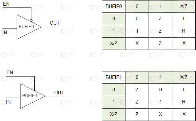
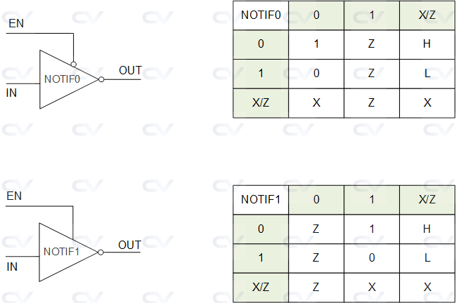
Bufif/Notif
Buffers and Inverters with an additional control signal to enable the output is available through bufif and notif primitives. These gates have a valid output only if the control signal is enabled else the output will be in high impedance. There are two versions of these, one with normal polarity of control indicated by a 1 like bufif1 and notif1 and second with inverted polarity of control indicated by a 0 like bufif0 and notif0.
In the previous session, we built a sequencer, and monitor to work along with the driver. Now, lets put all the three components inside a block called an Agent. Moreover, we'll tweak certain aspects of how they are instantiated and connected within the agent. By doing so, the agent will become re-usable and it'll be easier to just plug it in any environment. Its always the amount of configurability without changing the base code that will determine how re-usable a component is. Also, we'll create a scoreboard that can receive transactions from the monitor.
TestBench
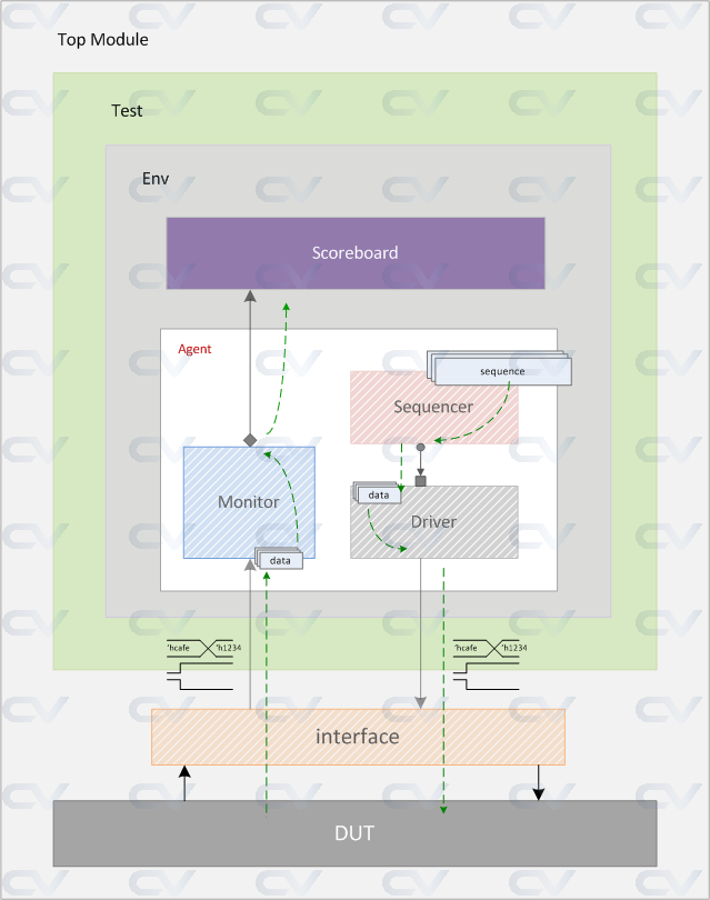
Agent
It's better to put the Sequencer, Monitor and Driver inside a uvm component called agent. Usually you'll develop an agent for a particular protocol like USB, AXI, PCIE, etc so that the agent can be plugged into any verification environment and becomes re-usable. To create an agent, simply put all the code inside the uvm_env in our previous session, inside a uvm_agent block and it's all set. Another feature that we want an agent to have, is the ability to make it passive or active.
A passive agent is one that has only a monitor so that it passively sits by the interface and monitors the transactions. This is useful when there is nothing particular to be driven to the DUT. An active agent is one which has all the three components especially the driver and sequencer, so that data can be sent to the DUT.
In Introduction, we saw that most of the verification components are inherited from uvm_report_object and hence they already have functions and methods to display messages.
Calling Functions
There are four basic reporting functions that can be used with different verbosity levels.
uvm_report_* ("TAG", $sformatf ("[Enter the display message]"), VERBOSITY_LEVEL);
where * can be either info, error, warning, fatal. UVM has six levels of verbosity with each one represented by an integer.
typedef enum {
   UVM_NONE    = 0,
   UVM_LOW     = 100,
   UVM_MEDIUM  = 200,
   UVM_HIGH    = 300,
   UVM_FULL    = 400,
   UVM_DEBUG   = 500
} uvm_verbosity;
