Components in a testbench often need to communicate with each other to exchange data and check output values of the design. A few mechanisms that allow components or threads to affect the control flow of data are shown in the table below.
| Events | Different threads synchronize with each other via event handles in a testbench |
| Semaphores | Different threads might need to access the same resource; they take turns by using a semaphore |
| Mailbox | Threads/Components need to exchange data with each other; data is put in a mailbox and sent |
What are Events ?
An event is a way to synchronize two or more different processes. One process waits for the event to happen while another process triggers the event. When the event is triggered, the process waiting for the event will resume execution.
event
event eventA; // Creates an event called "eventA"
-> operator
->eventA; // Any process that has access to "eventA" can trigger the event
	@eventA; 						// Use "@" operator to wait for an event
	wait (eventA.triggered);		// Or use the wait statement with "eventA.triggered"
module tb_top;
	event eventA; 		// Declare an event handle called  "eventA"

	initial begin
		fork
			waitForTrigger (eventA);    // Task waits for eventA to happen
			#5 ->eventA;                // Triggers eventA
		join
	end

	// The event is passed as an argument to this task. It simply waits for the event
	// to be triggered
	task waitForTrigger (event eventA);
		$display ("[%0t] Waiting for EventA to be triggered", $time);
		wait (eventA.triggered);
		$display ("[%0t] EventA has triggered", $time);
	endtask
endmodule
[0] Waiting for EventA to be triggered
[5] EventA has triggered
ncsim: *W,RNQUIE: Simulation is complete.
Click here to read more about a SystemVerilog event !
What's a semaphore ?
Let's say you wanted to rent a room in the library for a few hours. The admin desk will give you a key to use the room for the time you have requested access. After you are done with your work, you will return the key to the admin, which will then be given to someone else who wants to use the same room. This way two people will not be allowed to use the room at the same time. The key is a semaphore in this context.
A semaphore is used to control access to a resource and is known as a mutex (mutually exclusive) because only one entity can have the semaphore at a time.
module tb_top;
   semaphore key; 				// Create a semaphore handle called "key"

   initial begin
      key = new (1); 			// Create only a single key; multiple keys are also possible
      fork
         personA (); 			// personA tries to get the room and puts it back after work
         personB (); 			// personB also tries to get the room and puts it back after work
         #25 personA (); 		// personA tries to get the room a second time
      join_none
   end

   task getRoom (bit [1:0] id);
      $display ("[%0t] Trying to get a room for id[%0d] ...", $time, id);
      key.get (1);
      $display ("[%0t] Room Key retrieved for id[%0d]", $time, id);
   endtask

   task putRoom (bit [1:0] id);
      $display ("[%0t] Leaving room id[%0d] ...", $time, id);
      key.put (1);
      $display ("[%0t] Room Key put back id[%0d]", $time, id);
   endtask

   // This person tries to get the room immediately and puts
   // it back 20 time units later
   task personA ();
      getRoom (1);
      #20 putRoom (1);
   endtask

  // This person tries to get the room after 5 time units and puts it back after
  // 10 time units
   task personB ();
      #5  getRoom (2);
      #10 putRoom (2);
   endtask
endmodule
[0] Trying to get a room for id[1] ...
[0] Room Key retrieved for id[1]
[5] Trying to get a room for id[2] ...
[20] Leaving room id[1] ...
[20] Room Key put back id[1]
[20] Room Key retrieved for id[2]
[25] Trying to get a room for id[1] ...
[30] Leaving room id[2] ...
[30] Room Key put back id[2]
[30] Room Key retrieved for id[1]
[50] Leaving room id[1] ...
[50] Room Key put back id[1]
Note the following about semaphores.
- A semaphore object key is declared and created using
new ()function. Argument tonew ()defines the number of keys. - You get the key by using the
get ()keyword which will wait until a key is available (blocking) - You put the key back using the
put ()keyword
Click here to read more about a SystemVerilog semaphore !
What's a mailbox ?
A mailbox is like a dedicated channel established to send data between two components.
For example, a mailbox can be created and the handles be passed to a data generator and a driver. The generator can push the data object into the mailbox and the driver will be able to retrieve the packet and drive the signals onto the bus.
// Data packet in this environment
class transaction;
   rand bit [7:0] data;

   function display ();
      $display ("[%0t] Data = 0x%0h", $time, data);
   endfunction
endclass

// Generator class - Generate a transaction object and put into mailbox
class generator;
   mailbox mbx;

   function new (mailbox mbx);
      this.mbx = mbx;
   endfunction

   task genData ();
      transaction trns = new ();
      trns.randomize ();
      trns.display ();
      $display ("[%0t] [Generator] Going to put data packet into mailbox", $time);
      mbx.put (trns);
      $display ("[%0t] [Generator] Data put into mailbox", $time);
   endtask
endclass

// Driver class - Get the transaction object from Generator
class driver;
   mailbox mbx;

   function new (mailbox mbx);
      this.mbx = mbx;
   endfunction

   task drvData ();
      transaction drvTrns = new ();
      $display ("[%0t] [Driver] Waiting for available data", $time);
      mbx.get (drvTrns);
      $display ("[%0t] [Driver] Data received from Mailbox", $time);
      drvTrns.display ();
   endtask
endclass

// Top Level environment that will connect Gen and Drv with a mailbox
module tb_top;
   mailbox   mbx;
   generator Gen;
   driver    Drv;

   initial begin
      mbx = new ();
      Gen = new (mbx);
      Drv = new (mbx);

      fork
         #10 Gen.genData ();
         Drv.drvData ();
      join_none
   end
endmodule
[0] [Driver] Waiting for available data
[10] Data = 0x9d
[10] [Generator] Put data packet into mailbox
[10] [Generator] Data put into mailbox
[10] [Driver] Data received from Mailbox
[10] Data = 0x9d
ncsim: *W,RNQUIE: Simulation is complete.
Click here to read more about a SystemVerilog mailbox !
What is functional coverage ?
Functional coverage is a measure of what functionalities/features of the design have been exercised by the tests. This can be useful in constrained random verification (CRV) to know what features have been covered by a set of tests in a regression.
Design
module modN_ctr
  # (parameter N = 10,
     parameter WIDTH = 4)

  ( input   clk,
    input   rstn,
   	output  reg[WIDTH-1:0] out);

  always @ (posedge clk) begin
    if (!rstn) begin
      out <= 0;
    end else begin
      if (out == N-1)
        out <= 0;
      else
        out <= out + 1;
    end
  end
endmodule
Testbench
module tb;
  parameter N = 10;
  parameter WIDTH = 4;

  reg clk;
  reg rstn;
  wire [WIDTH-1:0] out;

  modN_ctr u0  ( 	.clk(clk),
                	.rstn(rstn),
                	.out(out));

  always #10 clk = ~clk;

  initial begin
    {clk, rstn} <= 0;

    $monitor ("T=%0t rstn=%0b out=0x%0h", $time, rstn, out);
    repeat(2) @ (posedge clk);
    rstn <= 1;

    repeat(20) @ (posedge clk);
    $finish;
  end
endmodule
ncsim> run
T=0 rstn=0 out=0xx
T=10 rstn=0 out=0x0
T=30 rstn=1 out=0x0
T=50 rstn=1 out=0x1
T=70 rstn=1 out=0x2
T=90 rstn=1 out=0x3
T=110 rstn=1 out=0x4
T=130 rstn=1 out=0x5
T=150 rstn=1 out=0x6
T=170 rstn=1 out=0x7
T=190 rstn=1 out=0x8
T=210 rstn=1 out=0x9
T=230 rstn=1 out=0xa
T=250 rstn=1 out=0x0
T=270 rstn=1 out=0x1
T=290 rstn=1 out=0x2
T=310 rstn=1 out=0x3
T=330 rstn=1 out=0x4
T=350 rstn=1 out=0x5
T=370 rstn=1 out=0x6
T=390 rstn=1 out=0x7
T=410 rstn=1 out=0x8
Simulation complete via $finish(1) at time 430 NS + 0
SystemVerilog offers much flexibility in building complicated data structures through the different types of arrays.
Static Arrays
A static array is one whose size is known before compilation time. In the example shown below, a static array of 8-bit wide is declared, assigned some value and iterated over to print its value.
module tb;
	bit [7:0] 	m_data; 	// A vector or 1D packed array

	initial begin
		// 1. Assign a value to the vector
		m_data = 8'hA2;

		// 2. Iterate through each bit of the vector and print value
		for (int i = 0; i < $size(m_data); i++) begin
			$display ("m_data[%0d] = %b", i, m_data[i]);
		end
	end
endmodule
We need to have an environment known as a testbench to run any kind of simulation on the design.
Click here to refresh basic concepts of a simulation
What is the purpose of a testbench ?
A testbench allows us to verify the functionality of a design through simulations. It is a container where the design is placed and driven with different input stimulus.
- Generate different types of input stimulus
- Drive the design inputs with the generated stimulus
- Allow the design to process input and provide an output
- Check the output with expected behavior to find functional defects
- If a functional bug is found, then change the design to fix the bug
- Perform the above steps until there are no more functional defects
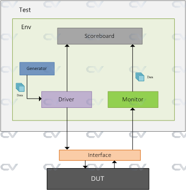
Components of a testbench
The example shown in Introduction is not modular, scalable, flexible or even re-usable because of the way DUT is connected, and how signals are driven. Let's take a look at a simple testbench and try to understand about the various components that facilitate data transfer from and to the DUT.
| Component | Description |
|---|---|
| Generator | Generates different input stimulus to be driven to DUT |
| Interface | Contains design signals that can be driven or monitored |
| Driver | Drives the generated stimulus to the design |
| Monitor | Monitor the design input-output ports to capture design activity |
| Scoreboard | Checks output from the design with expected behavior |
| Environment | Contains all the verification components mentioned above |
| Test | Contains the environment that can be tweaked with different configuration settings |
What is DUT ?
DUT stands for Design Under Test and is the hardware design written in Verilog or VHDL. DUT is a term typically used in post validation of the silicon once the chip is fabricated. In pre validation, it is also called as Design Under Verification, DUV in short.
// All verification components are placed in this top testbench module
module tb_top;

	// Declare variables that need to be connected to the design instance
	// These variables are assigned some values that in turn gets transferred to
	// the design as inputs because they are connected with the ports in the design
	reg clk;
	wire en;
	wire wr;
	wire data;

	// Instantiate the design module and connect the variables declared above
	// with the ports in the design
	design myDsn ( .clk (clk),
	               .en  (en),
	               .wr  (wr),
	               . ...
	               .rdata);

	// Develop rest of the testbench and write stimulus that can be driven to the design
endmodule
Click here for a complete SystemVerilog testbench example !
