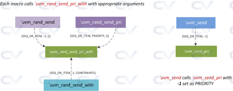
We have already seen how to use `uvm_do set of macros. They automatically create a new object via calls to `uvm_create, randomize the item and send it to a sequencer. If we already have a data object that we simply want to send to a sequencer, we can use `uvm_send. There are different variations to this macro, just like `uvm_do_*.
All behavioral code is written inside module and endmodule. It may or may not have ports defined to allow signals to enter the block as input or escape the block as output.
Module
The empty module in the example below is called testbench. You can name it whatever you like, except that it should be alphanumeric, and can contain '_'.
module testbench;

endmodule
What is Verilog ?
Verilog is a hardware description language (HDL) that is used to describe digital systems and circuits in the form of code. It was developed by Gateway Design Automation in the mid-1980s and later acquired by Cadence Design Systems.
Verilog is widely used for design and verification of digital and mixed-signal systems, including both application-specific integrated circuits (ASICs) and field-programmable gate arrays (FPGAs). It supports a range of levels of abstraction, from structural to behavioral, and is used for both simulation-based design and synthesis-based design.
The language is used to describe digital circuits hierarchically, starting with the most basic elements such as logic gates and flip-flops and building up to more complex functional blocks and systems. It also supports a range of modeling techniques, including gate-level, RTL-level, and behavioral-level modeling.
What was used before Verilog ?
Before the development of Verilog, the primary hardware description language (HDL) used for digital circuit design and verification was VHDL (VHSIC Hardware Description Language). VHDL was developed in the 1980s by the U.S. Department of Defense as part of the Very High-Speed Integrated Circuit (VHSIC) program to design and test high-speed digital circuits.
VHDL is a complex language that enables designers to describe digital systems using a range of abstraction levels, from the low-level transistor and gate levels up to complex hierarchical systems. It was designed to be more descriptive and flexible than earlier HDLs, such as ABEL (Advanced Boolean Expression Language), ISP (Integrated System Synthesis Procedure), and CUPL (Compiler for Universal Programmable Logic).
Despite the development of Verilog and its increasing popularity since the 1980s, VHDL remains a widely used HDL, particularly in Europe and in the military and aerospace industries. Today, both Verilog and VHDL are widely used in digital circuit design and verification, with many companies and organizations using a combination of the two languages.
Why is Verilog better than its predecessor languages ?
Verilog introduced several important improvements over its predecessor languages, which helped make it a more popular and effective HDL for digital circuit design and verification. Here are a few reasons why Verilog is considered better than its predecessor HDLs:
- Simpler syntax: Verilog has a simpler syntax compared to VHDL, which allows designers to write code more quickly and with fewer errors.
- Better support for behavioral modeling: Verilog provides better support for describing the behavior and functionality of digital designs. It supports a range of modeling techniques, from gate-level to behavioral-level modeling, which makes it easier to describe the behavior of complex digital circuits.
- Higher level of abstraction: Verilog provides a higher level of abstraction than its predecessor languages. It enables designers to describe digital circuits using concepts such as modules and ports, which makes the design process more efficient.
- Better tool support: Due to its increasing popularity, Verilog has better tool support than its predecessor languages. Verilog has a range of integrated development environments (IDEs) and simulation tools available, which makes it easier to design and verify digital circuits.
How is Verilog useful ?
Verilog creates a level of abstraction that helps hide away the details of its implementation and technology.
For example, the design of a D flip-flop would require the knowledge of how the transistors need to be arranged to achieve a positive-edge triggered FF and what the rise, fall and clk-Q times required to latch the value onto a flop among many other technology oriented details. Power dissipation, timing and the ability to drive nets and other flops would also require a more thorough understanding of the physical characteristics of a transistor.
Verilog helps us to focus on the behavior and leave the rest to be sorted out later.
Verilog Code Example
The following Verilog code describes the behavior of a counter. The counter counts up if the up_down signal is 1, and down if its value is 0. It also resets the counter if the signal rstn becomes 0, making it an active-low reset.
	module ctr (input  				up_down,
									clk,
									rstn,
	            output reg [2:0] 	out);

		always @ (posedge clk)
			if (!rstn)
				out <= 0;
			else begin
				if (up_down)
					out <= out + 1;
				else
					out <= out - 1;
			end
	endmodule
The simple example shown above illustrates how all the physical implementation details (interconnection of underlying logic gates like NAND and NOR) have been hidden while still providing a clear idea of how the counter functions.
ctr is a module that represents an up/down counter, and it is possible to choose the actual physical implementation of the design from a wide variety of different styles of flops optimized for area, power and performance. They are usually compiled into libraries and will be available for us to select within EDA tools at a later stage in the design process.
How is Verilog different from software languages like C and Java ?
Verilog is a hardware description language (HDL) used to describe digital circuits and systems, while C and Java are software programming languages used to write code that runs on general-purpose computers. Here are some of the main differences between Verilog and programming languages like C and Java:
- Purpose: Verilog is used to describe digital circuits and systems, while C and Java are used to write software programs that run on computers.
- Syntax: Verilog has a different syntax than C and Java, as it is designed to describe the behavior of digital circuits rather than the execution of software instructions. For example, Verilog describes the properties of wires, registers, and logic gates, while C and Java define variables, functions, and control loops.
- Execution: Verilog is used to describe how digital circuits should behave, but it doesn't directly execute code. Instead, the Verilog code is compiled into a hardware configuration that can be implemented in a physical circuit or FPGA. C and Java code, on the other hand, is compiled into machine code that can be executed directly by a computer processor.
- Testing and Verification: Verilog is typically used to simulate the behavior of digital systems before they are physically implemented, while C and Java programs are usually tested and verified through software-based simulations or code reviews.
- Nesting of Design: In Verilog, the designs can be created as modules and can be reused which is not in the case of programming languages like C and Java where the code is written for a specific purpose.
Overall, Verilog is a specialized language designed specifically for digital circuit design and isn't used for general-purpose programming like C and Java. While there are some similarities in syntax and programming concepts between these languages, the primary focus and application of Verilog is on the design, simulation, and implementation of digital circuits and systems.
What may replace Verilog in the future ?
It's difficult to predict exactly what may replace Verilog in the future, but there are several emerging technologies and languages that may have an impact on the future of digital system design and verification.
One technology that may affect the future of digital system design is High-Level Synthesis (HLS), which is a technique for automatically generating hardware designs from high-level descriptions in languages like C, C++, and SystemC. HLS allows designers to express their design intents and functionality at a higher level of abstraction, rather than specifying the details of logic gates and register transfers in Verilog or VHDL. This could enable more efficient and rapid design of digital systems, and allow designers to explore more design space in a shorter period of time.
Another technology that may impact the future of digital system design is machine learning and artificial intelligence (AI), which have the potential to significantly streamline the design and verification process of digital systems. For example, machine learning algorithms can be used to automatically optimize and generate hardware designs, reducing the need for manual design efforts.
There are also emerging HDLs that are trying to address some of the limitations of Verilog and VHDL, such as Chisel and MyHDL, which are based on more modern programming concepts and provide higher-level abstractions.
uvm_comparer is the standalone class used to set a policy for doing comparisons and determines how miscompares are counted. Every uvm_object instance has a compare() method for performing comparisons with another object. A policy object can be passed along to set parameters like depth of comparison, verbosity, maximum number of miscompares etc - an extra layer of flexibility. uvm_comparer also has a set of comparison methods for integers, strings, real numbers and objects.
Note that the number of miscompares is stored in an internal variable called "result", which gets incremented upon every such occurrence. Hence, if you are using the same object to compare two different items, the number of miscompares shown in the end might not be correct. It is advised to clear the "result" variable for every new comparison. This is only valid if you are directly using an object like in the example shown below.
When the uvm_comparer object is passed onto uvm_object::compare() method, the comparison policy will be set, and result will be cleared. If no uvm_comparer object is passed along, then it will take the default global level uvm_comparer policy object.
Example
This example will build upon the How to use uvm_printer set of data objects.
class base_test extends uvm_test;
   `uvm_component_utils (base_test)

   my_data obj0, obj1;
   derivative dv0, dv1;

   uvm_comparer uc0;

   function new (string name = "base_test", uvm_component parent);
      super.new (name, parent);
   endfunction

   virtual function void build_phase (uvm_phase phase);
      super.build_phase (phase);
      obj0 = my_data::type_id::create ("obj0");
      obj1 = my_data::type_id::create ("obj1");
      uc0 = new();
   endfunction

   virtual task run_phase (uvm_phase phase);

      cfg_comparer();
      // Do not use the same uvm_compare object to do multiple comparisons, like shown below
      // The example is a demonstration of the different methods of uvm_compare
      // NOTE: There's an internal variable "result" that stores the number of miscompares.
      // This variable will continue to be incremented for every mismatch, until cleared manually

      `uvm_info ("COMPARE", "Trying out compare_field", UVM_MEDIUM)
      uc0.compare_field ("compare_field1", 7, 7, 2);            // pass
      uc0.compare_field ("compare_field2", 8'd45, 8'd8, 2);     // fail

      `uvm_info ("COMPARE", "Trying out field_int", UVM_MEDIUM)
      uc0.compare_field_int ("field_int1", 64'hface_deaf_feed_cafe, 64'hfabe_deaf_feed_cafe, 64);  // fail
      uc0.compare_field_int ("field_int2", 64'habcd_ef12_3456_7890, 64'habcd_ef12_3456_7890, 64);  // pass

      uc0.compare_field_int ("field_int3", 64'hface_deaf_feed_cafe, 64'h7ace_deaf_feed_cafe, 63);  // pass
      uc0.compare_field_int ("field_int4", 64'hface_deaf_feed_cafe, 64'h8abe_deaf_feed_cafe, 64);  // fail

      uc0.compare_field_int ("field_int5", 68'hbbbb_face_deaf_feed_cafe, 68'haaaa_8abe_deaf_feed_cafe, 68); //  won't work; nothing happens
      uc0.compare_field ("field", 68'hb_face_deaf_feed_cafe, 68'haa_8abe_deaf_feed_cafe, 68); // fail: will work with field, because size > 64

      `uvm_info ("COMPARE", "Trying out compare_object", UVM_MEDIUM)
      void'(obj0.randomize());
      void'(obj1.randomize());
      uc0.compare_object ("object1", obj0, obj1);  // fail
      obj1.copy (obj0);
      uc0.compare_object ("object2", obj0, obj1);  // pass

      `uvm_info ("COMPARE", "Trying out compare_string", UVM_MEDIUM)
      uc0.compare_string ("string1", "Hello", "World");   // fail
      uc0.compare_string ("string2", "Hello", "Hello");   // pass


      // Proper Usage: Set the configuration for uvm_comparer and pass it to compare()
      // The "result" variable is cleared before comparison starts within uvm_object::compare()
      obj0.name = "Apple";
      obj0.m_format0.m_color.fav = "magenta";
      obj0.m_format0.m_color.unfav = "yellow";

      obj1.name = "Orange";
      obj1.m_format0.m_color.fav = "magenta";
      obj1.m_format0.m_color.unfav = "green";

      cfg_comparer();
      void'(obj0.randomize());
      obj1.compare (obj0, uc0);

      // randomize and compare again
      void'(obj0.randomize());
      obj1.compare (obj0, uc0);


   endtask

   virtual function cfg_comparer();
      uc0.show_max = 20;     // total number of miscompares to be printed
      uc0.verbosity = UVM_MEDIUM;
   endfunction

endclass
UVM_INFO @ 0: reporter [RNTST] Running test base_test...
UVM_INFO ./tb/test_pkg.sv(43) @ 0: uvm_test_top [COMPARE] Trying out compare_field
UVM_INFO @ 0: reporter [MISCMP] Miscompare for compare_field2: lhs = 'h1 : rhs = 'h0
UVM_INFO ./tb/test_pkg.sv(47) @ 0: uvm_test_top [COMPARE] Trying out field_int
UVM_INFO @ 0: reporter [MISCMP] Miscompare for field_int1: lhs = 'hfacedeaffeedcafe : rhs = 'hfabedeaffeedcafe
UVM_INFO @ 0: reporter [MISCMP] Miscompare for field_int4: lhs = 'hfacedeaffeedcafe : rhs = 'h8abedeaffeedcafe
UVM_INFO @ 0: reporter [MISCMP] Miscompare for field: lhs = 'hbfacedeaffeedcafe : rhs = 'ha8abedeaffeedcafe
UVM_INFO ./tb/test_pkg.sv(57) @ 0: uvm_test_top [COMPARE] Trying out compare_object
UVM_INFO @ 0: reporter [MISCMP] Miscompare for object1.data: lhs = 'h5a : rhs = 'h47
UVM_INFO @ 0: reporter [MISCMP] Miscompare for object1.addr: lhs = 'h1 : rhs = 'h2
UVM_INFO @ 0: reporter [MISCMP] Miscompare for object1.m_format0.header: lhs = 'hb : rhs = 'h2
UVM_INFO @ 0: reporter [MISCMP] Miscompare for object1.m_format0.footer: lhs = 'h0 : rhs = 'h7
UVM_INFO @ 0: reporter [MISCMP] Miscompare for object1.m_format0.body: lhs = 'h1 : rhs = 'h2
UVM_INFO @ 0: reporter [MISCMP] Miscompare for object1.m_format0.m_color.color: lhs = 'h8 : rhs = 'h2
UVM_INFO @ 0: reporter [MISCMP] 10 Miscompare(s) for object obj1@2722 vs. obj0@2687
UVM_INFO @ 0: reporter [MISCMP] 10 Miscompare(s) for object obj1@2722 vs. obj0@2687
UVM_INFO ./tb/test_pkg.sv(64) @ 0: uvm_test_top [COMPARE] Trying out compare_string
UVM_INFO @ 0: reporter [MISCMP] Miscompare for string1: lhs = "Hello" : rhs = "World"
UVM_INFO @ 0: reporter [MISCMP] Miscompare for obj1.data: lhs = 'h5a : rhs = 'hee
UVM_INFO @ 0: reporter [MISCMP] Miscompare for obj1.addr: lhs = 'h1 : rhs = 'h2
UVM_INFO @ 0: reporter [MISCMP] Miscompare for obj1.m_format0.header: lhs = 'hb : rhs = 'hf
UVM_INFO @ 0: reporter [MISCMP] Miscompare for obj1.m_format0.body: lhs = 'h1 : rhs = 'h2
UVM_INFO @ 0: reporter [MISCMP] Miscompare for obj1.m_format0.m_color.color: lhs = 'h8 : rhs = 'h7
UVM_INFO @ 0: reporter [MISCMP] Miscompare for obj1.m_format0.m_color.enable: lhs = 'h0 : rhs = 'h1
UVM_INFO @ 0: reporter [MISCMP] 6 Miscompare(s) for object obj0@2687 vs. obj1@2722
UVM_INFO @ 0: reporter [MISCMP] Miscompare for obj1.data: lhs = 'h5a : rhs = 'h2d
UVM_INFO @ 0: reporter [MISCMP] Miscompare for obj1.addr: lhs = 'h1 : rhs = 'h3
UVM_INFO @ 0: reporter [MISCMP] Miscompare for obj1.m_format0.header: lhs = 'hb : rhs = 'h9
UVM_INFO @ 0: reporter [MISCMP] Miscompare for obj1.m_format0.footer: lhs = 'h0 : rhs = 'h6
UVM_INFO @ 0: reporter [MISCMP] Miscompare for obj1.m_format0.enable: lhs = 'h1 : rhs = 'h0
UVM_INFO @ 0: reporter [MISCMP] Miscompare for obj1.m_format0.m_color.color: lhs = 'h8 : rhs = 'h0
UVM_INFO @ 0: reporter [MISCMP] Miscompare for obj1.m_format0.m_color.enable: lhs = 'h0 : rhs = 'h1
UVM_INFO @ 0: reporter [MISCMP] 7 Miscompare(s) for object obj0@2687 vs. obj1@2722

--- UVM Report catcher Summary ---
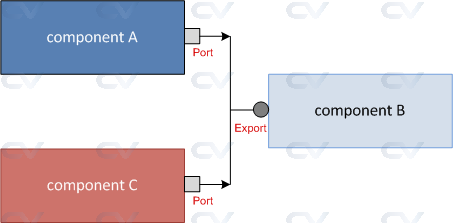
We have seen the scenario in TLM - Put, where data sent to componentB is executed using the put() method defined in B. Let us consider the case where there are two components A and C connected to B's export. Then, any data object sent by either componentA or componentC will be received by componentB and operated upon by the same put() method. If there's a need to be able to process them separately, you would need to have two separate put() methods.