The SystemVerilog standard specifies that signals in a design possess both a type and a data type. The type designates whether the signal is a net or a variable, while the data type defines the value system of that net or variable which are 0, 1, X and Z.
4-state Data Types
Types that can have unknown (X) and high-impedance (Z) value in addition to zero (0) and one (1) are called 4-state types. In Verilog, all nets (eg. wire) and variables (eg. reg) use 4-state values. Note that reg can only be driven in procedural blocks like always and initial while wire can only be used in assign statements.
logic
SystemVerilog introduces a new 4-state data type called logic that can be driven in both procedural blocks and continuous assign statements. However, a signal with more than one driver needs to be declared a net-type such as wire so that SystemVerilog can resolve the final value based on strength.
module tb;
	logic [3:0]  my_data; 		// Declare a 4-bit logic type variable
	logic        en; 			// Declare a 1-bit logic type variable

	initial begin
    	$display ("my_data=0x%0h en=%0b", my_data, en);    	// Default value of logic type is X
		my_data = 4'hB; 									// logic datatype can be driven in initial/always blocks
      	$display ("my_data=0x%0h en=%0b", my_data, en);
      	#1;
      	$display ("my_data=0x%0h en=%0b", my_data, en);
	end

  	assign en = my_data[0]; 								// logic datatype can also be driven via assign statements
endmodule
ncsim> run
my_data=0xx en=x
my_data=0xb en=x
my_data=0xb en=1
ncsim: *W,RNQUIE: Simulation is complete.
- Usage
- Examples
- Verilog assign statement
- Verilog always block
- Syntax
- What is the sensitivity list ?
- What is the always block used for ?
- What happens if there is no sensitivity list ?
- Sequential Element Design Example
- Combinational Element Design Example
- Synthesis
- Verilog initial block
- Syntax
- What is the initial block used for ?
- When does an initial block start and end ?
- What happens if there is a delay element ?
- How many initial blocks are allowed in a module ?
- Synthesis
The bins construct allows the creation of a separate bin for each value in the given range of possible values of a coverage point variable.
Usage
	coverpoint mode {
		// Manually create a separate bin for each value
		bins zero = {0};
		bins one  = {1};

		// Allow SystemVerilog to automatically create separate bins for each value
		// Values from 0 to maximum possible value is split into separate bins
		bins range[] = {[0:$]};

		// Create automatic bins for both the given ranges
		bins c[] = { [2:3], [5:7]};

		// Use fixed number of automatic bins. Entire range is broken up into 4 bins
		bins range[4] = {[0:$]};

		// If the number of bins cannot be equally divided for the given range, then
		// the last bin will include remaining items; Here there are 13 values to be
		// distributed into 4 bins which yields:
		// [1,2,3] [4,5,6] [7,8,9] [10, 1, 3, 6]
		bins range[4] = {[1:10], 1, 3, 6};

		// A single bin to store all other values that don't belong to any other bin
		bins others = default;
	}
Examples
module tb;
  bit [2:0] mode;

  // This covergroup does not get sample automatically because
  // the sample event is missing in declaration
  covergroup cg;
    coverpoint mode {
    	bins one = {1};
    	bins five = {5};
    }
  endgroup

  // Stimulus : Simply randomize mode to have different values and
  // manually sample each time
  initial begin
    cg cg_inst = new();
    for (int i = 0; i < 5; i++) begin
	  #10 mode = $random;
      $display ("[%0t] mode = 0x%0h", $time, mode);
      cg_inst.sample();
    end
    $display ("Coverage = %0.2f %%", cg_inst.get_inst_coverage());
  end

endmodule
ncsim> run
[10] mode = 0x4
[20] mode = 0x1
[30] mode = 0x1
[40] mode = 0x3
[50] mode = 0x5
Coverage = 100.00 %
ncsim: *W,RNQUIE: Simulation is complete.
Automatic Bins
  covergroup cg;
    coverpoint mode {

      // Declares a separate bin for each values -> Here there will 8 bins
      bins range[] = {[0:$]};
    }
  endgroup
4 out of the total possible 8 values have been sampled and hence coverage is 50%.
ncsim> run
[10] mode = 0x4
[20] mode = 0x1
[30] mode = 0x1
[40] mode = 0x3
[50] mode = 0x5
Coverage = 50.00 %
ncsim: *W,RNQUIE: Simulation is complete.
Fixed Number of automatic bins
  covergroup cg;
    coverpoint mode {

      // Declares 4 bins for the total range of 8 values
      // So bin0->[0:1] bin1->[2:3] bin2->[4:5] bin3->[6:7]
      bins range[4] = {[0:$]};
    }
  endgroup
mode never got a value of 6 or 7 and hence bin3 does not get hit. But all the other bins are hit and hence coverage is 75%.
ncsim> run
[10] mode = 0x4
[20] mode = 0x1
[30] mode = 0x1
[40] mode = 0x3
[50] mode = 0x5
Coverage = 75.00 %
ncsim: *W,RNQUIE: Simulation is complete.
Split fixed number of bins between a given range
  covergroup cg;
    coverpoint mode {

      // Defines 3 bins
      // Two bins for values from 1:4, and one bin for value 7
      // bin1->[1,2] bin2->[3,4], bin3->7
      bins range[3] = {[1:4], 7};
    }
  endgroup
Only 2/3 of the bins were hit and hence coverage is at 66.67%. To be specific, bin1 and bin2 were hit because mode was sampled to have 1 and [3,4] respectively.
ncsim> run
[10] mode = 0x4
[20] mode = 0x1
[30] mode = 0x1
[40] mode = 0x3
[50] mode = 0x5
Coverage = 66.67 %
ncsim: *W,RNQUIE: Simulation is complete.
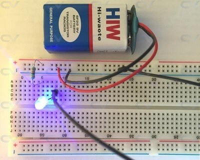
Signals of type wire or a similar wire like data type requires the continuous assignment of a value. For example, consider an electrical wire used to connect pieces on a breadboard. As long as the +5V battery is applied to one end of the wire, the component connected to the other end of the wire will get the required voltage.
In Verilog, this concept is realized by the assign statement where any wire or other similar wire like data-types can be driven continuously with a value. The value can either be a constant or an expression comprising of a group of signals.
An always block is one of the procedural blocks in Verilog. Statements inside an always block are executed sequentially.
Syntax
always @ (event)
	[statement]

always @ (event) begin
	[multiple statements]
end
The always block is executed at some particular event. The event is defined by a sensitivity list.
What is the sensitivity list ?
A sensitivity list is the expression that defines when the always block should be executed and is specified after the @ operator within parentheses ( ). This list may contain either one or a group of signals whose value change will execute the always block.
In the code shown below, all statements inside the always block get executed whenever the value of signals a or b change.
// Execute always block whenever value of "a" or "b" change
always @ (a or b) begin
	[statements]
end
What is the always block used for ?
An always block can be used to realize combinational or sequential elements. A sequential element like flip flop becomes active when it is provided with a clock and reset. Similarly, a combinational block becomes active when one of its input values change. These hardware blocks are all working concurrently independent of each other. The connection between each is what determines the flow of data. To model this behavior, an always block is made as a continuous process that gets triggered and performs some action when a signal within the sensitivity list becomes active.
In the following example, all statements within the always block get executed at every positive edge of the signal clk.
// Execute always block at positive edge of signal "clk"
always @ (posedge clk) begin
	[statements]
end
What happens if there is no sensitivity list ?
The always block repeats continuously throughout the duration of a simulation. The sensitivity list brings along a certain sense of timing i.e. whenever any signal in the sensitivity list changes, the always block is triggered. If there are no timing control statments within an always block, the simulation will hang because of a zero-delay infinite loop !
Example
The example shown below is an always block that attempts to invert the value of the signal clk. The statement is executed after every 0 time units. Hence, it executes forever because of the absence of a delay in the statement.
// always block is started at time 0 units
// But when is it supposed to be repeated ?
// There is no time control, and hence it will stay and
// be repeated at 0 time units only. This continues
// in a loop and simulation will hang !
always clk = ~clk;
Even if the sensitivity list is empty, there should be some other form of time delay. Simulation time is advanced by a delay statement within the always construct as shown below. Now, the clock inversion is done after every 10 time units.
always #10 clk = ~clk;
Note: Explicit delays are not synthesizable into logic gates !
Hence real Verilog design code always require a sensitivity list.
Sequential Element Design Example
The code shown below defines a module called tff that accepts a data input, clock and active-low reset. The output gets inverted whenever d is found to be 1 at the positive edge of clock. Here, the always block is triggered either at the positive edge of clk or the negative edge of rstn.
What happens at the positive edge of clock ?
The following events happen at the positive edge of clock and is repeated for all positive edge of clock.
- First
ifblock checks value of active-low reset rstn - If rstn is zero, then output q should be reset to default value of 0
- If rstn is one, then it means reset is not applied and should follow default behavior
- If the previous step is false:
- Check value of d and if it is found to be one, then invert value of q
- If d is 0, then maintain value of q
module tff (input  		d,
						clk,
						rstn,
			output reg 	q);

	always @ (posedge clk or negedge rstn) begin
		if (!rstn)
			q <= 0;
		else
			if (d)
				q <= ~q;
			else
				q <= q;
	end
endmodule
What happens at the negative edge of reset ?
The following events happen at negative edge of rstn and happen at all such occurrences.
- First
ifblock checks value of active-low reset rstn. At negative edge of the signal, its value is 0. - If value of rstn is 0, then it means reset is applied and output should be reset to default value of 0
- The case where value of rstn is 1 is not considered because the current event is negative edge of the rstn
Combinational Element Design Example
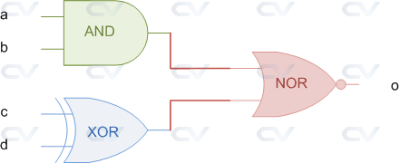
An always block can also be used in the design of combinational blocks. For example the following digital circuit represents a combination of three different logic gates that provide a certain output at signal o.
The code shown below is a module with four input ports and a single output port called o. The always block is triggered whenever any of the signals in the sensitivity list changes in value. Output signal is declared as type reg in the module port list because it is used in a procedural block. All signals used in a procedural block should be declared as type reg.
module combo (	input 	a,
      			input	b,
              	input	c,
              	input	d,
  	            output reg o);

  always @ (a or b or c or d) begin
    o <= ~((a & b) | (c^d));
  end

endmodule
See that the signal o becomes 1 whenever the combinational expression on the RHS becomes true. Similarly o becomes 0 when RHS is false.
Simulation Output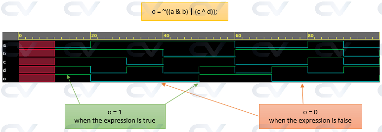
Synthesis
It is possible for an always block to not be synthesis friendly, if it does not follow one of the following templates.
// Template #1: Use for combinational logic, all inputs mentioned in
// sensitivity list ensures that it infers a combo block
always @ (all_inputs) begin
	// Combinational logic
end

// Template #2: Use of a if condition without else can cause a latch
// because the previous value has to be held since new value is not
// defined by a missing else clause
always @ (all_inputs) begin
	if (enable) begin
		// latch value assignments
	end
end

// Template #3: Use clock in sensitivity list for sequential elements
always @ (posedge clk) begin
	// behavior to do at posedge clock
end

// Template #4: Use clock and async reset in sensitivity list
always @ (posedge clk or negedge resetn) begin
	if (! resetn) begin
		// behavior to do during reset
	end else begin
		// behavior when not in reset
	end
end
A set of Verilog statements are usually executed sequentially in a simulation. These statements are placed inside a procedural block. There are mainly two types of procedural blocks in Verilog - initial and always
Syntax
	initial
		[single statement]

	initial begin
		[multiple statements]
	end
What is the initial block used for ?
An initial block is not synthesizable and hence cannot be converted into a hardware schematic with digital elements. Hence initial blocks do not serve much purpose than to be used in simulations. These blocks are primarily used to initialize variables and drive design ports with specific values.
When does an initial block start and end ?
An initial block is started at the beginning of a simulation at time 0 unit. This block will be executed only once during the entire simulation. Execution of an initial block finishes once all the statements within the block are executed.
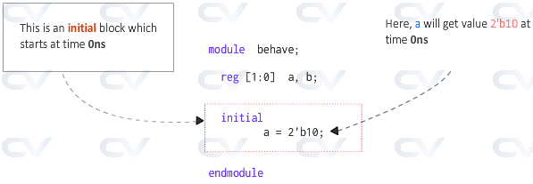
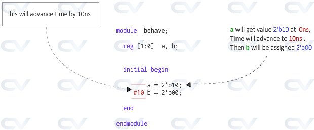
The image shown above has a module called behave which has two internal signals called a and b. The initial block has only one statement and hence it is not necessary to place the statement within begin and end. This statement assigns the value 2'b10 to a when the initial block is started at time 0 units.
What happens if there is a delay element ?
The code shown below has an additional statement that assigns some value to the signal b. However this happens only after 10 time units from execution of previous statement. This means that a is assigned first with the given value and then after 10 time units, b is assigned to 0.
How many initial blocks are allowed in a module ?
There are no limits to the number of initial blocks that can be defined inside a module.
The code shown below has three initial blocks all of which are started at the same time and run in parallel. However, depending on the statements and the delays within each initial block, the time taken to finish the block may vary.
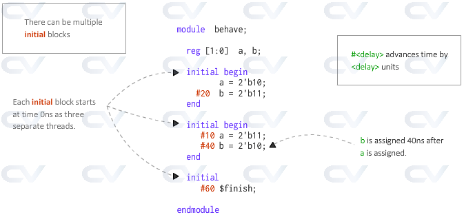
In this example, the first block has a delay of 20 units, while the second has a total delay of 50 units (10 + 40) and the last block has a delay of 60 units. Hence the simulation takes 60 time units to complete since there is atleast one initial block still running until 60 time units.
$finish is a Verilog system task that tells the simulator to terminate the current simulation.
If the last block had a delay of 30 time units like shown below, the simulation would have ended at 30 time units thereby killing all the other initial blocks that are active at that time.
	initial begin
		#30 $finish;
	end
Synthesis
An initial block is not synthesizable.
