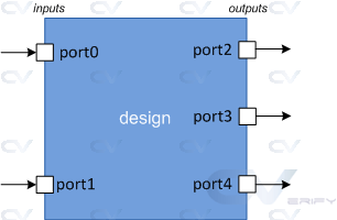
Ports are a set of signals that act as inputs and outputs to a particular module and are the primary way of communicating with it. Think of a module as a fabricated chip placed on a PCB and it becomes quite obvious that the only way to communicate with the chip is through its pins. Ports are like pins and are used by the design to send and receive signals from the outside world.
Types of Ports
| Port | Description |
|---|---|
| Input | The design module can only receive values from outside using its input ports |
| Output | The design module can only send values to the outside using its output ports |
| Inout | The design module can either send or receive values using its inout ports |
Ports are by default considered as nets of type wire.
Syntax
Ports declared as inout can act as both input and output.
	input  [net_type] [range] list_of_names; 	// Input port
	inout  [net_type] [range] list_of_names; 	// Input & Output port
	output [net_type] [range] list_of_names; 	// Output port driven by a wire
	output [var_type] [range] list_of_names; 	// Output port driven by a variable
Example
In the code shown below, there are three input ports, one output port and one inout port.
module  my_design ( input wire			clk,
                    input 					en,
                    input 					rw,
                    inout [15:0]	  data,
                    output 					int );

	// Design behavior as Verilog code

endmodule
It is illegal to use the same name for multiple ports.
	input  aport;         // First declaration - valid
	input  aport;         // Error - already declared
	output aport;         // Error - already declared
There are ways to group a set of statements together that are syntactically equivalent to a single statement and are known as block statements. There are two kinds of block statements: sequential and parallel.
Sequential
Statements are wrapped using begin and end keywords and will be executed sequentially in the given order, one after the other. Delay values are treated relative to the time of execution of the previous statement. After all the statements within the block are executed control may be passed elsewhere.
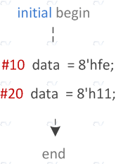
module design0;
	bit [31:0] data;

	// "initial" block starts at time 0
	initial begin

		// After 10 time units, data becomes 0xfe
		#10   data = 8'hfe;
		$display ("[Time=%0t] data=0x%0h", $time, data);

		// After 20 time units, data becomes 0x11
		#20   data = 8'h11;
		$display ("[Time=%0t] data=0x%0h", $time, data);
	end
endmodule
In the example above, first statement in the begin-end block will be executed at 10 time units, and the second statement at 30 time units because of the relative nature. It is 20 time units after execution of the previous statement.
ncsim> run
[Time=10] data=0xfe
[Time=30] data=0x11
ncsim: *W,RNQUIE: Simulation is complete.
A function is meant to do some processing on the input and return a single value, whereas a task is more general and can calculate multiple result values and return them using output and inout type arguments. Tasks can contain simulation time consuming elements such as @, posedge and others.
Syntax
A task need not have a set of arguments in the port list, in which case it can be kept empty.
	// Style 1
	task [name];
		input  [port_list];
		inout  [port_list];
		output [port_list];
		begin
			[statements]
		end
	endtask

	// Style 2
	task [name] (input [port_list], inout [port_list], output [port_list]);
		begin
			[statements]
		end
	endtask

	// Empty port list
	task [name] ();
		begin
			[statements]
		end
	endtask
Often times we find certain pieces of code to be repetitive and called multiple times within the RTL. They mostly do not consume simulation time and might involve complex calculations that need to be done with different data values. In such cases, we can declare a function and place the repetitive code inside the function and allow it to return the result. This will reduce the amount of lines in the RTL drastically since all you need to do now is to do a function call and pass data on which the computation needs to be performed. In fact, this is very similar to the functions in C.
The purpose of a function is to return a value that is to be used in an expression. A function definition always start with the keyword function followed by the return type, name and a port list enclosed in parantheses. Verilog knows that a function definition is over when it finds the endfunction keyword. Note that a function shall have atleast one input declared and the return type will be void if the function does not return anything.
Syntax
	function [automatic] [return_type] name ([port_list]);
		[statements]
	endfunction
The keyword automatic will make the function reentrant and items declared within the task are dynamically allocated rather than shared between different invocations of the task. This will be useful for recursive functions and when the same function is executed concurrently by N processes when forked.
A module is a block of Verilog code that implements a certain functionality. Modules can be embedded within other modules and a higher level module can communicate with its lower level modules using their input and output ports.
Syntax
A module should be enclosed within module and endmodule keywords. Name of the module should be given right after the module keyword and an optional list of ports may be declared as well. Note that ports declared in the list of port declarations cannot be redeclared within the body of the module.
	module <name> ([port_list]);
		// Contents of the module
	endmodule

	// A module can have an empty portlist
	module name;
		// Contents of the module
	endmodule
All variable declarations, dataflow statements, functions or tasks and lower module instances if any, must be defined within the module and endmodule keywords. There can be multiple modules with different names in the same file and can be defined in any order.
Example
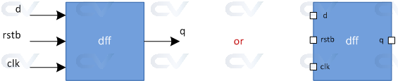
The module dff represents a D flip flop which has three input ports d , clk , rstn and one output port q . Contents of the module describe how a D flip flop should behave for different combinations of inputs. Here, input d is always assigned to output q at positive edge of clock if rstn is high because it is an active low reset.
// Module called "dff" has 3 inputs and 1 output port
module dff ( 	input 			d,
							input 			clk,
							input 			rstn,
							output reg	q);

	// Contents of the module
	always @ (posedge clk) begin
		if (!rstn)
			q <= 0;
		else
			q <= d;
	end
endmodule
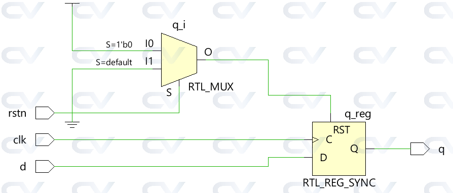
Hardware Schematic
This module will be converted into the following digital circuit during synthesis.
Note that you cannot have any code written outside a module !
What is the purpose of a module ?
A module represents a design unit that implements certain behavioral characteristics and will get converted into a digital circuit during synthesis. Any combination of inputs can be given to the module and it will provide a corresponding output. This allows the same module to be reused to form bigger modules that implement more complex hardware.
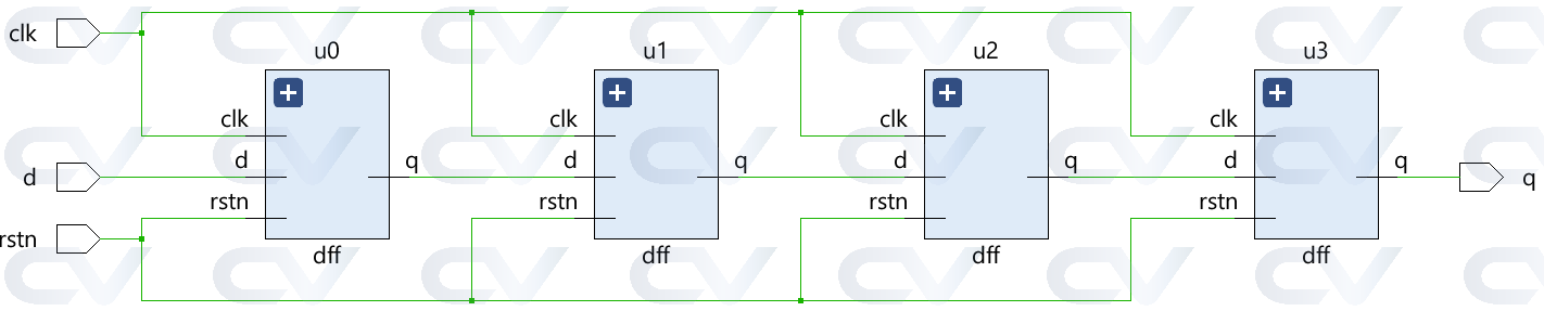
For example, the DFF shown above can be chained to form a shift register.
module shift_reg ( 	input 	d,
										input  	clk,
										input 	rstn,
										output 	q);

	wire [2:0] q_net;
	dff u0 (.d(d), 				.clk(clk), .rstn(rstn), .q(q_net[0]));
	dff u1 (.d(q_net[0]), .clk(clk), .rstn(rstn), .q(q_net[1]));
	dff u2 (.d(q_net[1]), .clk(clk), .rstn(rstn), .q(q_net[2]));
	dff u3 (.d(q_net[2]), .clk(clk), .rstn(rstn), .q(q));

endmodule
Hardware Schematic
Note that the dff instances are connected together with wires as described by the Verilog RTL module.
Instead of building up from smaller blocks to form bigger design blocks, the reverse can also be done. Consider the breakdown of a simple GPU engine into smaller components such that each can be represented as a module that implements a specific feature. The GPU engine shown below can be divided into five different sub-blocks where each perform a specific functionality. The bus interface unit gets data from outside into the design, which gets processed by another unit to extract instructions. Other units down the line process data provided by previous unit.
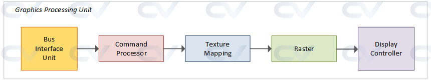
Each sub-block can be represented as a module with a certain set of input and output signals for communication with other modules and each sub-block can be further divided into more finer blocks as required.
What are top-level modules ?
A top-level module is one which contains all other modules. A top-level module is not instantiated within any other module.
For example, design modules are normally instantiated within top level testbench modules so that simulation can be run by providing input stimulus. But, the testbench is not instantiated within any other module because it is a block that encapsulates everything else and hence is the top-level module.
Design Top Level
The design code shown below has a top-level module called design. This is because it contains all other sub-modules requried to make the design complete. The submodules can have more nested sub-modules like mod3 inside mod1 and mod4 inside mod2. Anyhow, all these are included into the top level module when mod1 and mod2 are instantiated. So this makes the design complete and is the top-level module for the design.
	//---------------------------------
	//  Design code
	//---------------------------------
	module mod3 ( [port_list] );
		reg c;
		// Design code
	endmodule

	module mod4 ( [port_list] );
		wire a;
		// Design code
	endmodule

	module mod1 ( [port_list] );	 	// This module called "mod1" contains two instances
		wire 	y;

		mod3 	mod_inst1 ( ... ); 	 		// First instance is of module called "mod3" with name "mod_inst1"
		mod3 	mod_inst2 ( ... );	 		// Second instance is also of module "mod3" with name "mod_inst2"
	endmodule

	module mod2 ( [port_list] ); 		// This module called "mod2" contains two instances
		mod4 	mod_inst1 ( ... );			// First instance is of module called "mod4" with name "mod_inst1"
		mod4 	mod_inst2 ( ... );			// Second instance is also of module "mod4" with name "mod_inst2"
	endmodule

	// Top-level module
	module design ( [port_list]); 		// From design perspective, this is the top-level module
		wire 	_net;
		mod1 	mod_inst1 	( ... ); 			// since it contains all other modules and sub-modules
		mod2 	mod_inst2 	( ... );
	endmodule
Testbench Top Level
The testbench module contains stimulus to check functionality of the design and is primarily used for functional verification using simulation tools. Hence the design is instantiated and called d0 inside the testbench module. From a simulator perspective, testbench is the top level module.
	//-----------------------------------------------------------
	// Testbench code
	// From simulation perspective, this is the top-level module
	// because 'design' is instantiated within this module
	//-----------------------------------------------------------
	module testbench;
		design d0 ( [port_list_connections] );

		// Rest of the testbench code
	endmodule
Hierarchical Names
A hierarchical structure is formed when modules can be instantiated inside one another, and hence the top level module is called the root. Since each lower module instantiations within a given module is required to have different identifier names, there will not be any ambiguity in accessing signals. A hierarchical name is constructed by a list of these identifiers separated by dots . for each level of the hierarchy. Any signal can be accessed within any module using the hierarchical path to that particular signal.
	// Take the example shown above in top level modules
	design.mod_inst1 					// Access to module instance mod_inst1
	design.mod_inst1.y 					// Access signal "y" inside mod_inst1
	design.mod_inst2.mod_inst2.a		// Access signal "a" within mod4 module

	testbench.d0._net; 					// Top level signal _net within design module accessed from testbench
