A for loop in SystemVerilog repeats a given set of statements multiple times until the given expression is not satisfied. Like all other procedural blocks, the for loop requires multiple statements within it to be enclosed by begin and end keywords.
Syntax
For loop controls execution of its statements using a three step approach:
- Initialize the variables that affect how many times the loop is run
- Before executing the loop, check to see if the condition is true
- The modifier is executed at the end of each iteration, and jumps to step 2.
	for ( [initialization]; <condition>; [modifier])
		// Single statement

	for ( [initialization]; <condition>; [modifier]) begin
		// Multiple statements
	end
Example #1 - Array Iteration
In this example, we will iterate through a string array and print out its contents. The array array is initialized with 5 different names of fruits.
The for loop initialization declares a local variable called i that represents index of any element in the array. The conditional expression checks that i is less than size of the array. The modifier increments the value of i so that every iteration of the for loop operates on a different index.
module tb;
	string array [5] = '{"apple", "orange", "pear", "blueberry", "lemon"};

	initial begin
		for (int i = 0; i < $size(array); i++)
			$display ("array[%0d] = %s", i, array[i]);
	end
endmodule
ncsim> run
array[0] = apple
array[1] = orange
array[2] = pear
array[3] = blueberry
array[4] = lemon
ncsim: *W,RNQUIE: Simulation is complete.
Example #2 - Multiple Initializations
There can be multiple initializations done in the first part of a for loop. In the code shown below, variables i and j are both initialized as soon as the for loop is entered. To keep the example interesting, the index of each string pointed to by j is replaced by 0.
module tb;
	string array [5] = '{"apple", "orange", "pear", "blueberry", "lemon"};

	initial begin
      for (int i = 0, j = 2; i < $size(array); i++) begin
			array[i][j] = "0";
        $display ("array[%0d] = %s, %0dth index replaced by 0", i, array[i], j);
		end
	end
endmodule
ncsim> run
array[0] = ap0le, 2th index replaced by 0
array[1] = or0nge, 2th index replaced by 0
array[2] = pe0r, 2th index replaced by 0
array[3] = bl0eberry, 2th index replaced by 0
array[4] = le0on, 2th index replaced by 0
ncsim: *W,RNQUIE: Simulation is complete.
Example #3 - Adding multiple modifiers
In the code shown below, j is decremented after each iteration of the for loop along with incrementing i.
module tb;
	string array [5] = '{"apple", "orange", "pear", "blueberry", "lemon"};

	initial begin
      for (int i = 0, j = array[i].len() - 1; i <  $size(array); i++, j--) begin
			array[i][j] = "0";
        $display ("array[%0d] = %s, %0dth index replaced by 0", i, array[i], j);
		end
	end
endmodule
ncsim> run
array[0] = appl0, 4th index replaced by 0
array[1] = ora0ge, 3th index replaced by 0
array[2] = pe0r, 2th index replaced by 0
array[3] = b0ueberry, 1th index replaced by 0
array[4] = 0emon, 0th index replaced by 0
ncsim: *W,RNQUIE: Simulation is complete.
Verilog is a hardware description language and there is no requirement for designers to simulate their RTL designs to be able to convert them into logic gates. So what is the need to simulate?
Simulation is a technique of applying different input stimulus to the design at different times to check if the RTL code behaves the intended way. Essentially, simulation is a well-followed technique to verify the robustness of the design. It is also similar to how a fabricated chip will be used in the real world and how it reacts to different inputs.
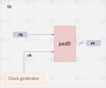
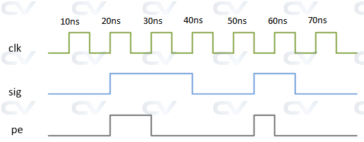
For example, the design above represents a positive edge detector with inputs clock and signal which are evaluated at periodic intervals to find the output pe as shown. Simulation allows us to view the timing diagram of related signals to understand how the design description in Verilog actually behaves.
There are several EDA companies that develop simulators capable of figuring out the outputs for various inputs to the design. Verilog is defined in terms of a discrete event execution model and different simulators are free to use different algorithms to provide the user with a consistent set of results. The Verilog code is divided into multiple processes and threads and may be evaluated at different times in the course of a simulation, which will be touched upon later.
Example
The testbench called tb is a container to hold a design module. However, in this example we have not used any design instances. There are two variables or signals that can be assigned certain values at specific times. clk represents a clock which is generated within the testbench. This is done by the always statement by alternating the clock's value after every 5ns. The initial block contains a set of statements that assign different values to both the signals at different times.
module tb;
  reg clk;
  reg sig;

  // Clock generation
  // Process starts at time 0ns and loops after every 5ns
  always #5 clk = ~clk;

  // Initial block : Process starts at time 0ns
  initial begin
    // This system task will print out the signal values everytime they change
    $monitor("Time = %0t clk = %0d sig = %0d", $time, clk, sig);

    // Also called stimulus, we simply assign different values to the variables
    // after some simulation "delay"
    sig = 0;
    #5 clk = 0;        // Assign clk to 0 at time 5ns
    #15  sig = 1;      // Assign sig to 1 at time 20ns (#5 + #15)
    #20  sig = 0;      // Assign sig to 0 at time 40ns (#5 + #15 + #20)
    #15  sig = 1;      // Assign sig to 1 at time 55ns (#5 + #15 + #20 + #15)
    #10  sig = 0;      // Assign sig to 0 at time 65ns (#5 + #15 + #20 + #15 + #10)
    #20 $finish;       // Finish simulation at time 85ns
  end
endmodule
The simulator provides the following output after execution of the above testbench.
ncsim> run
Time = 0 clk = x sig = 0
Time = 5 clk = 0 sig = 0
Time = 10 clk = 1 sig = 0
Time = 15 clk = 0 sig = 0
Time = 20 clk = 1 sig = 1
Time = 25 clk = 0 sig = 1
Time = 30 clk = 1 sig = 1
Time = 35 clk = 0 sig = 1
Time = 40 clk = 1 sig = 0
Time = 45 clk = 0 sig = 0
Time = 50 clk = 1 sig = 0
Time = 55 clk = 0 sig = 1
Time = 60 clk = 1 sig = 1
Time = 65 clk = 0 sig = 0
Time = 70 clk = 1 sig = 0
Time = 75 clk = 0 sig = 0
Time = 80 clk = 1 sig = 0
Simulation complete via $finish(1) at time 85 NS + 0
Display system tasks are mainly used to display informational and debug messages to track the flow of simulation from log files and also helps to debug faster. There are different groups of display tasks and formats in which they can print values.
Display/Write Tasks
Syntax
Both $display and $write display arguments in the order they appear in the argument list.
$display(<list_of_arguments>);
$write(<list_of_arguments>);
$write does not append the newline character to the end of its string, while $display does and can be seen from the example shown below.
Example
module tb;
  initial begin
    $display ("This ends with a new line ");
    $write ("This does not,");
    $write ("like this. To start new line, use newline char
");
    $display ("This always start on a new line !");
  end
endmodule
ncsim> run
This ends with a new line
This does not,like this. To start new line, use newline char
Hi there !
ncsim: *W,RNQUIE: Simulation is complete.
Verilog Strobes
$strobe prints the final values of variables at the end of the current delta time-step and has a similar format like $display.
module tb;
  initial begin
    reg [7:0] a;
    reg [7:0] b;

    a = 8'h2D;
    b = 8'h2D;

    #10;                  // Wait till simulation reaches 10ns
    b <= a + 1;           // Assign a+1 value to b

    $display ("[$display] time=%0t a=0x%0h b=0x%0h", $time, a, b);
    $strobe  ("[$strobe]  time=%0t a=0x%0h b=0x%0h", $time, a, b);

    #1;
    $display ("[$display] time=%0t a=0x%0h b=0x%0h", $time, a, b);
    $strobe  ("[$strobe]  time=%0t a=0x%0h b=0x%0h", $time, a, b);

  end
endmodule
Note that $strobe shows the final updated value of the variable b at time 10ns which is 0x2E, and $display picks that up only in the next simulation delta at 11ns.
ncsim> run
[$display] time=10 a=0x2d b=0x2d
[$strobe]  time=10 a=0x2d b=0x2e
[$display] time=11 a=0x2d b=0x2e
[$strobe]  time=11 a=0x2d b=0x2e
ncsim: *W,RNQUIE: Simulation is complete.
ncsim> exit
Difference between $display and $strobe
$display outputs values immediately when called while $strobe outputs values after all processes in the current time step have completed. When both tasks are used in the same time unit, $strobe will reflect changes made by nonblocking assignments that occur before its execution, while $display will show values as they were at the moment it was called.
Verilog Continuous Monitors
$monitor helps to automatically print out variable or expression values whenever the variable or expression in its argument list changes. It achieves a similar effect of calling $display after every time any of its arguments get updated.
module tb;
  initial begin
    reg [7:0] a;
    reg [7:0] b;

    a = 8'h2D;
    b = 8'h2D;

    #10;                  // Wait till simulation reaches 10ns
    b <= a + 1;           // Assign a+1 value to b

    $monitor ("[$monitor] time=%0t a=0x%0h b=0x%0h", $time, a, b);

    #1 b <= 8'hA4;
    #5 b <= a - 8'h33;
    #10 b <= 8'h1;

  end
endmodule
Note that $monitor is like a task that is spawned to run in the background of the main thread which monitors and displays value changes of its argument variables. A new $monitor task can be issued any number of times during simulation.
ncsim> run
[$monitor] time=10 a=0x2d b=0x2e
[$monitor] time=11 a=0x2d b=0xa4
[$monitor] time=16 a=0x2d b=0xfa
[$monitor] time=26 a=0x2d b=0x1
ncsim: *W,RNQUIE: Simulation is complete.
Verilog Format Specifiers
In order to print variables inside display functions, appropriate format specifiers have to be given for each variable.
| Argument | Description |
|---|---|
| %h, %H | Display in hexadecimal format |
| %d, %D | Display in decimal format |
| %b, %B | Display in binary format |
| %m, %M | Display hierarchical name |
| %s, %S | Display as a string |
| %t, %T | Display in time format |
| %f, %F | Display 'real' in a decimal format |
| %e, %E | Display 'real' in an exponential format |
module tb;
  initial begin
    reg [7:0]  a;
    reg [39:0] str = "Hello";
    time       cur_time;
    real       float_pt;

    a = 8'h0E;
    float_pt = 3.142;

    $display ("a = %h", a);
    $display ("a = %d", a);
    $display ("a = %b", a);

    $display ("str = %s", str);
    #200 cur_time = $time;
    $display ("time = %t", cur_time);
    $display ("float_pt = %f", float_pt);
    $display ("float_pt = %e", float_pt);
  end
endmodule
ncsim> run
a = 0e
a =  14
a = 00001110
str = Hello
time =                  200
float_pt = 3.142000
float_pt = 3.142000e+00
ncsim: *W,RNQUIE: Simulation is complete.
Verilog Escape Sequences
Some characters are considered special since they stand for other display purposes like new-line, tabs and form feeds. In order to print these special characters, each occurrence of such characters have to be escaped.
| Argument | Description |
|---|---|
| Newline character | |
| Tab character | |
| The character | |
| " | The " character |
| %% | The % character |
module tb;
  initial begin
    $write ("Newline character
");
    $display ("Tab character 	stop");
    $display ("Escaping  " %%");

/*
    // Compilation errors
    $display ("Without escaping ");       // ERROR : Unterminated string
    $display ("Without escaping "");       // ERROR : Unterminated string
*/
  end
endmodule
ncsim> run
Newline character

Tab character	stop
Escaping  " %
ncsim: *W,RNQUIE: Simulation is complete.
Lexical conventions in Verilog are similar to C in the sense that it contains a stream of tokens. A lexical token may consist of one or more characters and tokens can be comments, keywords, numbers, strings or white space. All lines should be terminated by a semi-colon ;.
Verilog is case-sensitive, so var_a and var_A are different.
Comments
There are two ways to write comments in Verilog.
- A single line comment starts with
//and tells Verilog compiler to treat everything after this point to the end of the line as a comment. - A multiple-line comment starts with
/*and ends with*/and cannot be nested.
However, single line comments can be nested in a multiple line comment.
// This is a single line comment

integer a;   // Creates an int variable called a, and treats everything to the right of // as a comment

/*
This is a
multiple-line or
block comment
*/

/* This is /*
an invalid nested
block comment */
*/

/* However,
// this one is okay
*/

// This is also okay
///////////// Still okay
Blocking
Blocking assignment statements are assigned using = and are executed one after the other in a procedural block. However, this will not prevent execution of statments that run in a parallel block.
module tb;
  reg [7:0] a, b, c, d, e;

  initial begin
    a = 8'hDA;
    $display ("[%0t] a=0x%0h b=0x%0h c=0x%0h", $time, a, b, c);
    b = 8'hF1;
    $display ("[%0t] a=0x%0h b=0x%0h c=0x%0h", $time, a, b, c);
    c = 8'h30;
    $display ("[%0t] a=0x%0h b=0x%0h c=0x%0h", $time, a, b, c);
  end

  initial begin
    d = 8'hAA;
    $display ("[%0t] d=0x%0h e=0x%0h", $time, d, e);
 	e = 8'h55;
    $display ("[%0t] d=0x%0h e=0x%0h", $time, d, e);
  end
endmodule
Note that there are two initial blocks which are executed in parallel when simulation starts. Statements are executed sequentially in each block and both blocks finish at time 0ns. To be more specific, variable a gets assigned first, followed by the display statement which is then followed by all other statements. This is visible in the output where variable b and c are 8'hxx in the first display statement. This is because variable b and c assignments have not been executed yet when the first $display is called.
ncsim> run
[0] a=0xda b=0xx c=0xx
[0] a=0xda b=0xf1 c=0xx
[0] a=0xda b=0xf1 c=0x30
[0] d=0xaa e=0xx
[0] d=0xaa e=0x55
ncsim: *W,RNQUIE: Simulation is complete.
