A SystemVerilog queue is a First In First Out scheme which can have a variable size to store elements of the same data type.
It is similar to a one-dimensional unpacked array that grows and shrinks automatically. They can also be manipulated by indexing, concatenation and slicing operators. Queues can be passed to tasks/functions as ref or non-ref arguments.
Types of Queues
A bounded queue has a specific size and can hold a limited number of entries. Shown below is a bounded queue of depth N and is full with N items and cannot accept more.

[data_type]  [name_of_queue] [$:N];

int 	bounded_queue [$:10]; 	// Depth 10
An unbounded queue can have an unlimited number of entries. Shown below is an unbounded queue which has 5 items and can accept more.
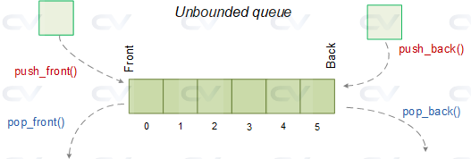
[data_type]  [name_of_queue] [$];

int 	unbounded_queue [$]; 	// Unlimited entries
A SystemVerilog case statement checks whether an expression matches one of a number of expressions and branches appropriately. The behavior is the same as in Verilog.
Click here to learn about Verilog case statements !
unique,unique0 case
All case statements can be qualified by unique or unique0 keywords to perform violation checks like we saw in if-else-if construct.
unique and unique0 ensure that there is no overlapping case items and hence can be evaluated in parallel. If there are overlapping case items, then a violation is reported.
- If more than one case item is found to match the given expression, then a violation is reported and the first matching expression is executed
- If no case item is found to match the given expression, then a violation is reported only for
unqiue
 unique0 does not report a violation if no items match the expression
unique : No items match for given expression
module tb;
  bit [1:0] 	abc;

  initial begin
    abc = 1;

    // None of the case items match the value in "abc"
    // A violation is reported here
    unique case (abc)
      0 : $display ("Found to be 0");
      2 : $display ("Found to be 2");
    endcase
  end
endmodule
ncsim> run
ncsim: *W,NOCOND: Unique case violation:  Every case item expression was false.
            File: ./testbench.sv, line = 9, pos = 14
           Scope: tb
            Time: 0 FS + 1

ncsim: *W,RNQUIE: Simulation is complete.
unique : More than one case item matches
module tb;
  bit [1:0] 	abc;

  initial begin
    abc = 0;

    // Multiple case items match the value in "abc"
    // A violation is reported here
    unique case (abc)
      0 : $display ("Found to be 0");
      0 : $display ("Again found to be 0");
      2 : $display ("Found to be 2");
    endcase
  end
endmodule
ncsim> run
Found to be 0
ncsim: *W,MCONDE: Unique case violation:  Multiple matching case item expressions at {line=10:pos=6 and line=11:pos=6}.
            File: ./testbench.sv, line = 9, pos = 14
           Scope: tb
            Time: 0 FS + 1

ncsim: *W,RNQUIE: Simulation is complete.
priority case
module tb;
  bit [1:0] 	abc;

  initial begin
    abc = 0;

    // First match is executed
    priority case (abc)
      0 : $display ("Found to be 0");
      0 : $display ("Again found to be 0");
      2 : $display ("Found to be 2");
    endcase
  end
endmodule
ncsim> run
Found to be 0
ncsim: *W,RNQUIE: Simulation is complete.
Till the previous stage we had defined and created everything required within the register environment. However which agent is responsible for driving these register transactions hadn't been defined.
class my_env extends uvm_env;
   `uvm_component_utils (my_env)

   my_agent       m_agent;
   reg_env        m_reg_env;

   function new (string name = "my_env", uvm_component parent);
      super.new (name, parent);
   endfunction

   virtual function void build_phase (uvm_phase phase);
      super.build_phase (phase);
      m_agent = my_agent::type_id::create ("m_agent", this);
      m_reg_env = reg_env::type_id::create ("m_reg_env", this);
   endfunction

   virtual function void connect_phase (uvm_phase phase);
      super.connect_phase (phase);
      m_agent.m_mon.mon_ap.connect (m_reg_env.m_apb2reg_predictor.bus_in);
      m_reg_env.m_ral_model.default_map.set_sequencer (m_agent.m_seqr, m_reg_env.m_reg2apb);
   endfunction

endclass
Modport lists with directions are defined in an interface to impose certain restrictions on interface access within a module. The keyword modport indicates that the directions are declared as if inside the module.
Syntax
	modport  [identifier]  (
		input  [port_list],
		output [port_list]
	);
Shown below is the definition of an interface myInterface which has a few signals and two modport declarations. The modport dut0 essentially states that the signals ack and sel are inputs and gnt and irq0 are outputs to whatever module uses this particular modport.
Similarly, another modport called dut1 is declared which states that gnt and irq0 are inputs and the other two are outputs for any module that uses modport dut1.
interface 	myInterface;
	logic 	ack;
	logic 	gnt;
	logic 	sel;
	logic 	irq0;

	// ack and sel are inputs to the dut0, while gnt and irq0 are outputs
	modport  dut0 (
		input 	ack, sel,
		output 	gnt, irq0
	);

	// ack and sel are outputs from dut1, while gnt and irq0 are inputs
	modport  dut1 (
		input 	gnt, irq0,
		output 	ack, sel
	);
endinterface
Example of named port bundle
In this style, the design will take the required correct modport definition from the interface object as mentioned in its port list. The testbench only needs to provide the whole interface object to the design.
	module dut0  ( myinterface.dut0  _if);
		...
	endmodule

	module dut1  ( myInterface.dut1 _if);
		...
	endmodule

	module tb;
		myInterface 	_if;
		dut0  	d0 	( .* );
		dut1 	d1 	( .* );
	endmodule
Example of connecting port bundle
In this style, the design simply accepts whatever directional information is given to it. Hence testbench is responsible to provide the correct modport values to the design.
	module dut0  ( myinterface  _if);
		...
	endmodule

	module dut1  ( myInterface _if);
		...
	endmodule

	module tb;
		myInterface 	_if;
		dut0  	d0 	( ._if (_if.dut0));
		dut1 	d1 	( ._if (_if.dut1));
	endmodule
What is the need for a modport ?
Nets declared within a simple interface is inout by default and hence any module connected to the same net, can either drive values or take values from it. In simple words, there are no restrictions on direction of value propagation. You could end up with an X on the net because both the testbench and the design are driving two different values to the same interface net. Special care should be taken by the testbench writer to ensure that such a situation does not happen. This can be inherently avoided by the use of modports.
Example of connecting to generic interface
A module can also have a generic interface as the portlist. The generic handle can accept any modport passed to it from the hierarchy above.
	module dut0  ( interface  _if);
		...
	endmodule

	module dut1  ( interface _if);
		...
	endmodule

	module tb;
		myInterface 	_if;
		dut0  	d0 	( ._if (_if.dut0));
		dut1 	d1 	( ._if (_if.dut1));
	endmodule
Design Example
Lets consider two modules master and slave connected by a very simple bus structure. Assume that the bus is capable of sending an address and data which the slave is expected to capture and update the information in its internal registers. So the master always has to initiate the transfer and the slave is capable of indicating to the master whether it is ready to accept the data by its sready signal.
Interface
Shown below is an interface definition that is shared between the master and slave modules.
interface ms_if (input clk);
  logic sready;      // Indicates if slave is ready to accept data
  logic rstn;        // Active low reset
  logic [1:0] addr;  // Address
  logic [7:0] data;  // Data

  modport slave ( input addr, data, rstn, clk,
                 output sready);

  modport master ( output addr, data,
                  input  clk, sready, rstn);
endinterface
Design
Assume that the master simply iterates the address from 0 to 3 and sends data equal to the address multiplied by 4. The master should only send when the slave is ready to accept and is indicated by the sready signal.
// This module accepts an interface with modport "master"
// Master sends transactions in a pipelined format
// CLK    1   2   3   4   5   6
// ADDR   A0  A1  A2  A3  A0  A1
// DATA       D0  D1  D2  D3  D4
module master ( ms_if.master mif);
  always @ (posedge mif.clk) begin

  	// If reset is applied, set addr and data to default values
    if (! mif.rstn) begin
      mif.addr <= 0;
      mif.data <= 0;

    // Else increment addr, and assign data accordingly if slave is ready
    end else begin
    // Send new addr and data only if slave is ready
      if (mif.sready) begin
      	mif.addr <= mif.addr + 1;
      	mif.data <= (mif.addr * 4);

     // Else maintain current addr and data
      end else begin
        mif.addr <= mif.addr;
        mif.data <= mif.data;
      end
    end
  end
endmodule
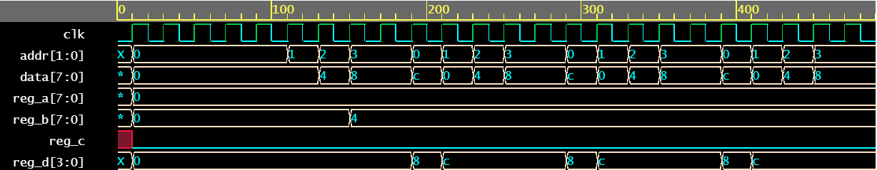
Assume that the slave accepts data for every addr and assigns them to internal registers. When the address wraps from 3 to 0, the slave requires 1 additional clock to become ready.
module slave (ms_if.slave sif);
  reg [7:0] reg_a;
  reg [7:0]	reg_b;
  reg 		reg_c;
  reg [3:0] reg_d;

  reg		dly;
  reg [3:0] addr_dly;


  always @ (posedge sif.clk) begin
    if (! sif.rstn) begin
      addr_dly <= 0;
    end else begin
      addr_dly <= sif.addr;
    end
  end

  always @ (posedge sif.clk) begin
    if (! sif.rstn) begin
      	reg_a <= 0;
    	reg_b <= 0;
    	reg_c <= 0;
    	reg_d <= 0;
  	end else begin
      case (addr_dly)
        0 : reg_a <= sif.data;
        1 : reg_b <= sif.data;
        2 : reg_c <= sif.data;
        3 : reg_d <= sif.data;
      endcase
    end
  end

  assign sif.sready = ~(sif.addr[1] & sif.addr[0]) | ~dly;

  always @ (posedge sif.clk) begin
    if (! sif.rstn)
      dly <= 1;
    else
      dly <= sif.sready;
  end

endmodule
The two design modules are tied together at a top level.
module d_top (ms_if tif);
	// Pass the "master" modport to master
  	master 	m0 (tif.master);

  	// Pass the "slave" modport to slave
  	slave 	s0 (tif.slave);
endmodule
Testbench
The testbench will pass the interface handle to the design, which will then assign master and slave modports to its sub-modules.
module tb;
  reg clk;
  always #10 clk = ~clk;

  ms_if 	if0 (clk);
  d_top 	d0  (if0);

  // Let the stimulus run for 20 clocks and stop
  initial begin
    clk <= 0;
    if0.rstn <= 0;
    repeat (5) @ (posedge clk);
    if0.rstn <= 1;

    repeat (20) @ (posedge clk);
    $finish;
  end
endmodule
Remember that the master initiates bus transactions and the slave captures data and stores it in its internal registers reg_* for the corresponding address.
Introduction covered the need for an interface, how to instantiate and connect the interface with a design. There are two ways in which the design can be written:
- By using an existing interface name to specifically use only that interface
- By using a generic interface handle to which any interface can be passed
Obviously, the generic method works best when interface definitions are updated to newer versions with a different name, and needs to support older designs that use it.
Example using a named bundle
In this case, the design references the actual interface name for access to its signals. The example below shows that both design modules myDesign and yourDesign declares a port in the port list called if0 of type myInterface to access signals.
	module myDesign  (  myInterface  if0,
	                    input logic  clk);
		always @ (posedge clk)
			if (if0.ack)
				if0.gnt <= 1;

		...
	endmodule

	module yourDesign (  myInterface 	if0,
						 input logic 	clk);
		...

	endmodule

	module tb;
		logic clk = 0;

		myInterface 	_if;

		myDesign 	md0 	(_if, clk);
		yourDesign	yd0 	(_if, clk);

	endmodule
