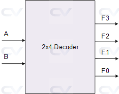
A decoder is a combinational circuit that converts a binary code into a set of output signals. It has N input lines and 2N output lines. The decoder takes the binary code on its N input lines and activates the output line corresponding to the binary code.
Combinational circuits are types of digital circuits that output a binary value, based on a set of input signals. These circuits are generally constructed using logic gates such as AND, OR, NOT, NAND, and NOR gates. They do not have any memory elements or feedback loops, meaning the output only depends on the current input conditions.
Combinational circuits are used for tasks that involve mathematical computations, such as adders and multipliers, as well as logic operations, such as reduction and comparison. They are widely used in digital systems and applications such as computers, calculators, and communication systems.
Universal gates are digital logic gates that can be used to implement any Boolean function without requiring other gates. In other words, any Boolean function can be expressed as a combination of one or more universal gates. The two most commonly used universal gates are the NAND gate and the NOR gate.
What is a K-Map and what is it used for ?
A Karnaugh map, also known as a K-Map, is a graphical representation of a truth table that simplifies Boolean algebra expressions. It is a tool used in digital electronics and computer science for optimizing logical functions to reduce the number of gates or circuits required to implement a logic function.
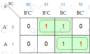
A K-Map is a table with binary values that are used to represent all possible input combinations for a given Boolean function. The table is arranged in a particular way so that adjacent cells have only one variable changing between them. This layout allows the identification of groups of adjacent cells with the same output value, which can be used to simplify and optimize the Boolean function.
Boolean logic is a type of logic that is used in computer programming and digital electronics to make logical decisions. It uses a binary system of 1's and 0's to represent true and false, and logical operators such as AND, OR, and NOT to combine and manipulate these values. Boolean logic is fundamental to many programming languages and is used in everything from creating basic IF/ELSE statements to more complex decision-making algorithms.
