What is the number system ?
The number system is a way of representing numerical values. It is a set of rules, symbols and processes that allow us to count, measure, and calculate numerical quantities. The most common number systems are the decimal system, which uses the digits 0-9, and the binary system, which uses only 0 and 1. Other number systems include octal, hexadecimal, and Roman numerals. Each number system has its own unique properties and applications, and is used in various fields such as mathematics, computer science, engineering, and physics.
What are all different applications of FIFO?
FIFOs (First-In-First-Out) are used in a wide range of applications where data needs to be buffered or stored temporarily. Some of the most common applications of FIFOs include:
Give the code for a mod-3 counter
A modulo-3 counter has 3 states (0, 1, 2) and requires 23 number of flip-flops.
module cntr_mod3 (input clk, rstn, output reg [1:0] out);
  always @(posedge clk) begin
    if (!rstn)
      out <= 0;
    else
      if (&out)
        out <= 0;
      else
      	out <= out + 1;
  end
endmodule
- Difference between $stop and $finish.
- Design frequency/2 circuit using D flip flop
- What is $random in Verilog ?
- What is the default value of wire and reg?
- Difference between inter and intra assignment delay.
- Illustrate how the infinite loops get created in the looping constructs like while and for.
- Illustrate the side-effects of a function return type without a range.
- What is #0 in Verilog and its usage?
- How to generate two different clocks in testbench ?
- Implement flip-flop using 2:1 MUX
Difference between $stop and $finish.
$stop is used to suspend the simulation at the point where it is called, simulator license is not released and still runs as a process in host operating system. User has to restart it, typically by manually resuming the simulation from the paused point.
$finish immediately terminates the simulation process and passes control back to the operating system, and license is released because simulation has exited.
$stop is useful for debugging and inspection of intermediate results in the design, allowing designers to examine signals, waveforms, or variables at a specific point in execution, while $finish is used at the end of the simulation, indicating that the design has completed its operation.
Design frequency/2 circuit using D flip flop
A frequency divider by 2 can be designed using a D flip-flop as follows:
    _________________
   |     ________    |
   |    |        |   |
   '--->|D     Q'|---'
        |        |
        |      Q |---- clk/2
        |___^____|
            |
 clk _______|
The input clock signal Clk is connected to the D input of the D flip-flop. The output of the flip-flop, Q, is connected back to the D input through an inverter to create a divide-by-2 circuit.
- When the clock rises from low to high, the D flip-flop captures the value of the D input and outputs it on Q.
- At the same time, the inverted output Q' feeds it back to the D input.
- Thus, the output Q changes state on every positive edge of the clock, resulting in a frequency that is half of the input frequency.
Note that the input clock signal should have a duty cycle close to 50% to ensure reliable operation of the flip-flop. It is also important to ensure that the setup and hold times of the flip-flop are met to avoid timing errors.
What is $random in Verilog ?
$random is a system task that generates a new 32-bit random integer on every call with a seed value of 0 by default. The optional seed value is used to specify the starting point for the random number generator, and if specified, $random generates the same sequence of random numbers every time it is called with the same seed value. It has the following syntax:
$random(seed);
What is the default value of wire and reg?
In Verilog, the default value of an uninitialized wire is 'z' or high-impedance and the default value of an uninitialized reg is 'x' or unknown. Read more on Verilog Data Types.
Difference between inter and intra assignment delay.
An intra-assignment delay specifies a delay that occurs within an assignment statement. It is specified using the # delay operator immediately following the driver in the assignment statement.
assign #5 a = b;
An inter-assignment delay specifies the delay between assignments to a signal. It is specified using the @(delay) or wait (delay) constructs.
initial
begin
    @(posedge clk) // This waits for a positive clock edge with a delay of 1 unit
    a = b;
    #2          // This introduces an inter-assignment delay of 2 time units
    a = c;
end
Read more on Verilog Inter and Intra Assignment Delay.
Illustrate how the infinite loops get created in the looping constructs like while and for.
Infinite loops occur in programming when a loop does not have a condition to stop the iteration. Let's take a look at how infinite loops can get created in various looping constructs.
reg over;

initial begin
	over = 0;

	while (!over) begin
		#10 $display("[%0t] In Loop", $time);
	end
end
The while loop will only exit if some other process changes over to 1, and it will run forever if this does not happen.
Here is another example with for loop which will run forever because of a width mismatch in the looping variable. The looping variable i goes from 0 to 7, wraps back to 0, counts up again and never reach the exit loop condition.
reg [2:0] i;

initial begin

	for (i = 0; i < 16; i = i+1) begin
		$display("[%0t] i = %0d", i);
	end
end
Illustrate the side-effects of a function return type without a range.
If the range of the function return type is not specified, Verilog assumes it to be a 1 bit scalar value. There would not be any compilation errors but it will result in a functional error.
module tb;

	// Should have been function [3:0] add(input [31:0] a, b);
	// Returns 1 bit value by default
  	function add(input [3:0] a, b);
    	return a + b;
  	endfunction

	initial begin
		$display("Sum = %0d", add(4, 5)); 	// Returns 1
	end
endmodule
Read more on Verilog Functions.
What is #0 in Verilog and its usage?
In Verilog, #0 is a delay specifier that represents zero time delay. It is processed after all active events at the current simulation time have been processed, and its usage is generally not recommended. Like all delays, it is not synthesizable either in designs.
module tb;
	reg [3:0] x;

	initial begin
      $monitor("[%0t] x = %0d", $time, x);

		x = 0;
		#10 x = 10;
	end

	initial begin
		#10;
		#0 x = 15;
	end
endmodule
In the above code, the #0 delay will make the variable x get value 15 at the end of 10 time units.
How to generate two different clocks in testbench ?
To generate two different clocks in a testbench, you can use two different initial or always blocks to toggle the two clock signals. Here's an example Verilog code for generating two clock signals with different frequencies using initial blocks:
module tb;

  reg clk1;
  reg clk2;

  initial begin
    clk1 = 1'b0;
    forever #10 clk1 = ~clk1; // Generate a clock with 50% duty cycle and 100ns frequency
  end

  initial begin
    clk2 = 1'b0;
    forever #5 clk2 = ~clk2; // Generate a clock with 50% duty cycle and 50ns frequency
  end

  // Rest of the testbench code
endmodule
In this code, two initial blocks are used to generate two clock signals, clk1 and clk2 . The forever loops in each block toggle the clock signal at a specific frequency using the `#` delay operator. You can use these clock signals to drive different components in your design or to test the asynchronous behavior of your design.
Implement flip-flop using 2:1 MUX
A flip-flop can be implemented using a 2:1 MUX (multiplexer). Here's how you can implement a D flip-flop using a 2:1 MUX in Verilog:
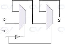
module dff_using_mux(input d, clk, output q);
  wire out1;

  assign out1 = ~clk ? d  : out1;
  assign q    =  clk ? q  : out1;

endmodule
What are the main data types in Verilog ?
In Verilog, there are several data types that can be used to represent different types of data. The main data types in Verilog include:
- Wire: A wire is used for simple connectivity between Verilog modules. It represents a net that can only have one driver and will be used as an output from one module and input to another.
- Reg: A reg is used to represent registers or memory elements in a Verilog design. It is used to store and manipulate data within a Verilog module.
- Integer: An integer is a data type used to represent signed integers in Verilog. It has a range of -2147483648 to 2147483647.
Read more on Verilog Data Types.
