The verilog assign statement is typically used to continuously drive a signal of wire datatype and gets synthesized as combinational logic. Here are some more design examples using the assign statement.
Example #1 : Simple combinational logic
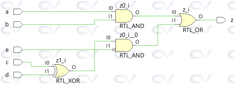
The code shown below implements a simple digital combinational logic which has an output wire z that is driven continuously with an assign statement to realize the digital equation.
module combo ( 	input 	a, b, c, d, e,
								output 	z);

	assign z = ((a & b) | (c ^ d) & ~e);

endmodule
The module combo gets elaborated into the following hardware schematic using synthesis tools and can be seen that the combinational logic is implemented with digital gates.
Testbench
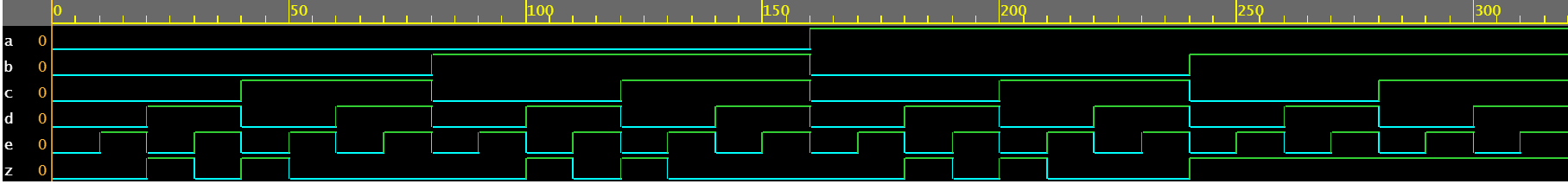
The testbench is a platform for simulating the design to ensure that the design does behave as expected. All combinations of inputs are driven to the design module using a for loop with a delay statement of 10 time units so that the new value is applied to the inputs after some time.
module tb;
	// Declare testbench variables
  reg a, b, c, d, e;
  wire z;
  integer i;

  // Instantiate the design and connect design inputs/outputs with
  // testbench variables
  combo u0 ( .a(a), .b(b), .c(c), .d(d), .e(e), .z(z));

  initial begin
  	// At the beginning of time, initialize all inputs of the design
  	// to a known value, in this case we have chosen it to be 0.
    a <= 0;
    b <= 0;
    c <= 0;
    d <= 0;
    e <= 0;

    // Use a $monitor task to print any change in the signal to
    // simulation console
    $monitor ("a=%0b b=%0b c=%0b d=%0b e=%0b z=%0b",
              a, b, c, d, e, z);

    // Because there are 5 inputs, there can be 32 different input combinations
    // So use an iterator "i" to increment from 0 to 32 and assign the value
    // to testbench variables so that it drives the design inputs
    for (i = 0; i < 32; i = i + 1) begin
      {a, b, c, d, e} = i;
      #10;
    end
  end
endmodule
ncsim> run
a=0 b=0 c=0 d=0 e=0 z=0
a=0 b=0 c=0 d=0 e=1 z=0
a=0 b=0 c=0 d=1 e=0 z=1
a=0 b=0 c=0 d=1 e=1 z=0
a=0 b=0 c=1 d=0 e=0 z=1
a=0 b=0 c=1 d=0 e=1 z=0
a=0 b=0 c=1 d=1 e=0 z=0
a=0 b=0 c=1 d=1 e=1 z=0
a=0 b=1 c=0 d=0 e=0 z=0
a=0 b=1 c=0 d=0 e=1 z=0
a=0 b=1 c=0 d=1 e=0 z=1
a=0 b=1 c=0 d=1 e=1 z=0
a=0 b=1 c=1 d=0 e=0 z=1
a=0 b=1 c=1 d=0 e=1 z=0
a=0 b=1 c=1 d=1 e=0 z=0
a=0 b=1 c=1 d=1 e=1 z=0
a=1 b=0 c=0 d=0 e=0 z=0
a=1 b=0 c=0 d=0 e=1 z=0
a=1 b=0 c=0 d=1 e=0 z=1
a=1 b=0 c=0 d=1 e=1 z=0
a=1 b=0 c=1 d=0 e=0 z=1
a=1 b=0 c=1 d=0 e=1 z=0
a=1 b=0 c=1 d=1 e=0 z=0
a=1 b=0 c=1 d=1 e=1 z=0
a=1 b=1 c=0 d=0 e=0 z=1
a=1 b=1 c=0 d=0 e=1 z=1
a=1 b=1 c=0 d=1 e=0 z=1
a=1 b=1 c=0 d=1 e=1 z=1
a=1 b=1 c=1 d=0 e=0 z=1
a=1 b=1 c=1 d=0 e=1 z=1
a=1 b=1 c=1 d=1 e=0 z=1
a=1 b=1 c=1 d=1 e=1 z=1
ncsim: *W,RNQUIE: Simulation is complete.
Example #2: Half Adder
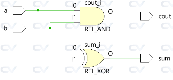
The half adder module accepts two scalar inputs a and b and uses combinational logic to assign the outputs sum and carry bit cout . The sum is driven by an XOR between a and b while the carry bit is obtained by an AND between the two inputs.
module ha ( input 	a, b,
						output	sum, cout);

	assign sum  = a ^ b;
	assign cout = a & b;
endmodule
Testbench
module tb;
	// Declare testbench variables
  reg a, b;
  wire sum, cout;
  integer i;

  // Instantiate the design and connect design inputs/outputs with
  // testbench variables
  ha u0 ( .a(a), .b(b), .sum(sum), .cout(cout));

  initial begin
  	// At the beginning of time, initialize all inputs of the design
  	// to a known value, in this case we have chosen it to be 0.
    a <= 0;
    b <= 0;

    // Use a $monitor task to print any change in the signal to
    // simulation console
    $monitor("a=%0b b=%0b sum=%0b cout=%0b", a, b, sum, cout);

    // Because there are only 2 inputs, there can be 4 different input combinations
    // So use an iterator "i" to increment from 0 to 4 and assign the value
    // to testbench variables so that it drives the design inputs
    for (i = 0; i < 4; i = i + 1) begin
      {a, b} = i;
      #10;
    end
  end
endmodule
ncsim> run
a=0 b=0 sum=0 cout=0
a=0 b=1 sum=1 cout=0
a=1 b=0 sum=1 cout=0
a=1 b=1 sum=0 cout=1
ncsim: *W,RNQUIE: Simulation is complete.

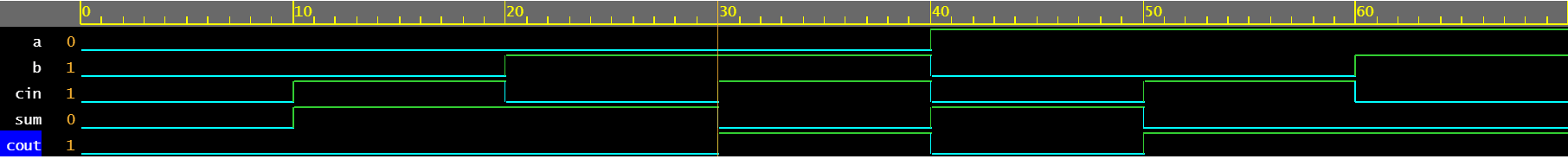
Example #3: Full Adder
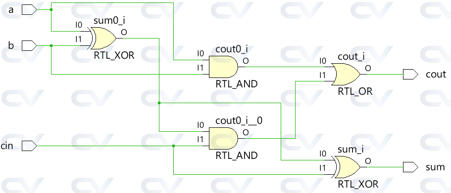
A full adder can be built using the half adder module shown above or the entire combinational logic can be applied as is with assign statements to drive the outputs sum and cout .
module fa (	input 	a, b, cin,
						output 	sum, cout);

	assign sum  = (a ^ b) ^ cin;
	assign cout = (a & b) | ((a ^ b) & cin);
endmodule
Testbench
module tb;
  reg a, b, cin;
  wire sum, cout;
  integer i;

  fa u0 ( .a(a), .b(b), .cin(cin), .sum(sum), .cout(cout));

  initial begin
    a <= 0;
    b <= 0;

    $monitor("a=%0b b=%0b cin=%0b sum=%0b cout=%0b", a, b, cin, sum, cout);

    for (i = 0; i < 7; i = i + 1) begin
      {a, b, cin} = i;
      #10;
    end
  end
endmodule
ncsim> run
a=0 b=0 cin=0 sum=0 cout=0
a=0 b=0 cin=1 sum=1 cout=0
a=0 b=1 cin=0 sum=1 cout=0
a=0 b=1 cin=1 sum=0 cout=1
a=1 b=0 cin=0 sum=1 cout=0
a=1 b=0 cin=1 sum=0 cout=1
a=1 b=1 cin=0 sum=0 cout=1
ncsim: *W,RNQUIE: Simulation is complete.
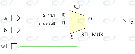
Example #4: 2x1 Multiplexer
The simple 2x1 multiplexer uses a ternary operator to decide which input should be assigned to the output c . If sel is 1, output is driven by a and if sel is 0 output is driven by b .
module mux_2x1 (input 	a, b, sel,
								output 	c);

	assign c = sel ? a : b;
endmodule
Testbench
module tb;
	// Declare testbench variables
  reg a, b, sel;
  wire c;
  integer i;

  // Instantiate the design and connect design inputs/outputs with
  // testbench variables
  mux_2x1 u0 ( .a(a), .b(b), .sel(sel), .c(c));

  initial begin
  	// At the beginning of time, initialize all inputs of the design
  	// to a known value, in this case we have chosen it to be 0.
    a <= 0;
    b <= 0;
    sel <= 0;

    $monitor("a=%0b b=%0b sel=%0b c=%0b", a, b, sel, c);

    for (i = 0; i < 3; i = i + 1) begin
      {a, b, sel} = i;
      #10;
    end
  end
endmodule
ncsim> run
a=0 b=0 sel=0 c=0
a=0 b=0 sel=1 c=0
a=0 b=1 sel=0 c=1
ncsim: *W,RNQUIE: Simulation is complete.

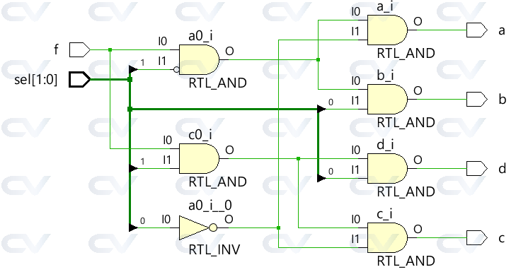
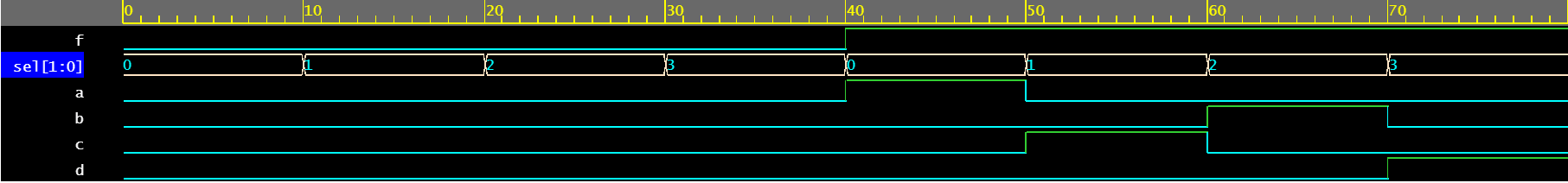
Example #5: 1x4 Demultiplexer
The demultiplexer uses a combination of sel and f inputs to drive the different output signals. Each output signal is driven by a separate assign statement. Note that the same signal is generally not recommended to be driven by different assign statements.
module demux_1x4 (	input 				f,
										input [1:0]	 	sel,
										output 				a, b, c, d);

	assign a = f & ~sel[1] & ~sel[0];
	assign b = f &  sel[1] & ~sel[0];
	assign c = f & ~sel[1] &  sel[0];
	assign d = f &  sel[1] &  sel[0];

endmodule
Testbench
module tb;
	// Declare testbench variables
  reg f;
  reg [1:0] sel;
  wire a, b, c, d;
  integer i;

  // Instantiate the design and connect design inputs/outputs with
  // testbench variables
  demux_1x4 u0 ( .f(f), .sel(sel), .a(a), .b(b), .c(c), .d(d));

  // At the beginning of time, initialize all inputs of the design
  // to a known value, in this case we have chosen it to be 0.
  initial begin
    f <= 0;
    sel <= 0;

    $monitor("f=%0b sel=%0b a=%0b b=%0b c=%0b d=%0b", f, sel, a, b, c, d);

    // Because there are 3 inputs, there can be 8 different input combinations
    // So use an iterator "i" to increment from 0 to 8 and assign the value
    // to testbench variables so that it drives the design inputs
    for (i = 0; i < 8; i = i + 1) begin
      {f, sel} = i;
      #10;
    end
  end
endmodule
ncsim> run
f=0 sel=0 a=0 b=0 c=0 d=0
f=0 sel=1 a=0 b=0 c=0 d=0
f=0 sel=10 a=0 b=0 c=0 d=0
f=0 sel=11 a=0 b=0 c=0 d=0
f=1 sel=0 a=1 b=0 c=0 d=0
f=1 sel=1 a=0 b=0 c=1 d=0
f=1 sel=10 a=0 b=1 c=0 d=0
f=1 sel=11 a=0 b=0 c=0 d=1
ncsim: *W,RNQUIE: Simulation is complete.
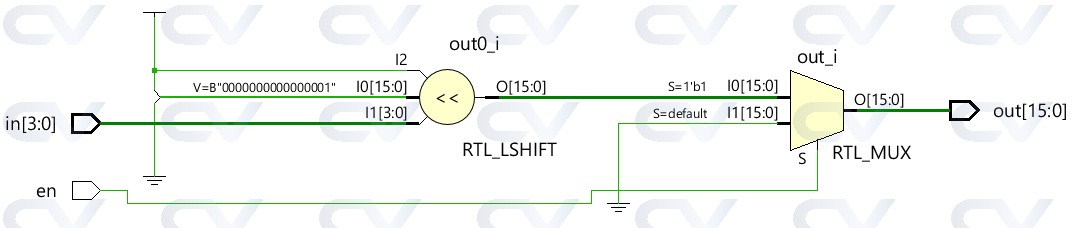
Example #6: 4x16 Decoder
module dec_3x8 ( 	input 					en,
									input 	[3:0] 	in,
									output  [15:0] 	out);

	assign out = en ? 1 << in: 0;
endmodule
Testbench
module tb;
  reg en;
  reg [3:0] in;
  wire [15:0] out;
  integer i;

  dec_3x8 u0 ( .en(en), .in(in), .out(out));

  initial begin
    en <= 0;
    in <= 0;

    $monitor("en=%0b in=0x%0h out=0x%0h", en, in, out);

    for (i = 0; i < 32; i = i + 1) begin
      {en, in} = i;
      #10;
    end
  end
endmodule
ncsim> run
en=0 in=0x0 out=0x0
en=0 in=0x1 out=0x0
en=0 in=0x2 out=0x0
en=0 in=0x3 out=0x0
en=0 in=0x4 out=0x0
en=0 in=0x5 out=0x0
en=0 in=0x6 out=0x0
en=0 in=0x7 out=0x0
en=0 in=0x8 out=0x0
en=0 in=0x9 out=0x0
en=0 in=0xa out=0x0
en=0 in=0xb out=0x0
en=0 in=0xc out=0x0
en=0 in=0xd out=0x0
en=0 in=0xe out=0x0
en=0 in=0xf out=0x0
en=1 in=0x0 out=0x1
en=1 in=0x1 out=0x2
en=1 in=0x2 out=0x4
en=1 in=0x3 out=0x8
en=1 in=0x4 out=0x10
en=1 in=0x5 out=0x20
en=1 in=0x6 out=0x40
en=1 in=0x7 out=0x80
en=1 in=0x8 out=0x100
en=1 in=0x9 out=0x200
en=1 in=0xa out=0x400
en=1 in=0xb out=0x800
en=1 in=0xc out=0x1000
en=1 in=0xd out=0x2000
en=1 in=0xe out=0x4000
en=1 in=0xf out=0x8000
ncsim: *W,RNQUIE: Simulation is complete.

UVM register model allows access to the DUT registers using the front door as we have seen before in the register environment.
This means that all register read and write operations in the environment are converted into bus transactions that get driven into the bus interface of the design, just like any other hardware component in a typical system would do. Because these accesses are sent as valid bus transactions, it consumes bus cycles. This is the recommended way to verify registers in any design as it closely resembles with what happens in the system.
What are backdoor accesses ?
UVM also allows backdoor accesses which uses a simulator database to directly access the signals within the DUT. Write operations deposit a value onto the signal and read operations sample the current value from the register signal. Since registers are the leaf nodes in a digital system, depositing a new value in the middle of any design transitions should not cause any problem. However, the control logic that becomes active during a typical bus write operation will not be active and hence any logic connected to this may not work as expected.
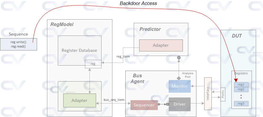
A backdoor access takes zero simulation time since the HDL values are directly accessed and do not consume a bus transaction. This is not the recommended way to verify register acesses in any design, but under certain circumstances, backdoor accesses help to enhance verification efforts using frontdoor mechanism.
Define backdoor HDL path
The simulator has to know the HDL path to the signal for which it is trying to do a backdoor operation. So, it is the responsibility of the user to specify the signal path in the register model for every register or for those registers which required backdoor access.
To enhance reuse and portability, the whole path is broken into multiple hierarchies. For example, the path to a given register can be split into the path from testbench top to subsystem top level, and from subsystem top to block level top and block level top to register block top and finally register block top to the given register. If the subsystem is reused in another design, only the section of HDL path from testbench top to the subsystem top level needs to be updated.
Example
Click here to refresh the design example in frontdoor access !
We'll add HDL paths for the traffic controller design example seen in frontdoor access example, and then perform some backdoor access writes and reads. HDL paths are added during register model construction. Basically they are added by certain function calls and hence can be done later after register model construction.
A uvm_object is the base class from which all other UVM classes for data and components are derived. So it is logical for this class to have a common set of functions and features that can be availed by all its derived classes.
Some of the common functions usually required is the ability to print its contents, copy contents from one object to another, and possibly compare two objects. UVM has many automation macros that get expanded into full code during compilation and implements these functions for all classes with ease.
Example
The purpose of this example is to show how UVM automation macros can be used to print variable contents easily.
A class called Object is derived from uvm_object thereby inheriting all functions within the parent class. A few variables of different data types are declared and an attempt is made to print the content of these variables after randomization.
There are different variations of `uvm_field_* macros for each data type and the variables have to be registered with the macro corresponding to its data type. UVM_DEFAULT indicates that the given variable should be used for all the default UVM automation macros implemented by the object which are copy, print, compare and record.
typedef enum {FALSE, TRUE} e_bool;
class Object extends uvm_object;

	rand e_bool 				m_bool;
  rand bit[3:0] 			m_mode;
  rand byte 					m_data[4];
  rand shortint 			m_queue[$];
  string							m_name;

  constraint c_queue { m_queue.size() == 3; }

  function new(string name = "Object");
    super.new(name);
    m_name = name;
  endfunction

  // Each variable has to be registered with a macro corresponding to its data
  // type. For example, "int" types use `uvm_field int, "enum" types use
  // `uvm_field_enum, and "string" use `uvm_field_string
  `uvm_object_utils_begin(Object)
  	`uvm_field_enum(e_bool, m_bool,	UVM_DEFAULT)
  	`uvm_field_int (m_mode,					UVM_DEFAULT)
  	`uvm_field_sarray_int(m_data,		UVM_DEFAULT)
  	`uvm_field_queue_int(m_queue,		UVM_DEFAULT)
  	`uvm_field_string(m_name,				UVM_DEFAULT)
  `uvm_object_utils_end
endclass
To test the above code, we'll simply use a base test class that will print contents of the object.
class base_test extends uvm_test;
  `uvm_component_utils(base_test)
  function new(string name = "base_test", uvm_component parent=null);
    super.new(name, parent);
  endfunction

  // In the build phase, create an object, randomize it and print
  // its contents
  function void build_phase(uvm_phase phase);
    Object obj = Object::type_id::create("obj");
    obj.randomize();
    obj.print();
  endfunction
endclass

module tb;
	initial begin
		run_test("base_test");
	end
endmodule
By default the UVM printer prints content of any object in a table format in which it specifies the name of the variable, data type of the variable, its size and the value. In the simulation output shown below, it can be seen that the object obj was randomized to the given values. It's quite interesting to note that even arrays (both static and queues) are printed with content of all their indices.
ncsim> run
UVM_INFO /playground_lib/uvm-1.2/src/base/uvm_root.svh(392) @ 0: reporter [UVM/RELNOTES]
----------------------------------------------------------------
UVM-1.2
(C) 2007-2014 Mentor Graphics Corporation
(C) 2007-2014 Cadence Design Systems, Inc.
(C) 2006-2014 Synopsys, Inc.
(C) 2011-2013 Cypress Semiconductor Corp.
(C) 2013-2014 NVIDIA Corporation
----------------------------------------------------------------

UVM_INFO @ 0: reporter [RNTST] Running test base_test...
-------------------------------------
Name       Type          Size  Value
-------------------------------------
obj        Object        -     @1899
  m_bool   e_bool        32    TRUE
  m_mode   integral      4     'hd
  m_data   sa(integral)  4     -
    [0]    integral      8     'h6c
    [1]    integral      8     'hf4
    [2]    integral      8     'he
    [3]    integral      8     'h58
  m_queue  da(integral)  3     -
    [0]    integral      16    'h3cb6
    [1]    integral      16    'h9ae9
    [2]    integral      16    'hd31d
  m_name   string        3     obj
-------------------------------------
UVM_INFO /playground_lib/uvm-1.2/src/base/uvm_report_server.svh(847) @ 0: reporter [UVM/REPORT/SERVER]
--- UVM Report Summary ---
Using do_print()
Using automation macros are not recommended these days because it introduces quite a lot of additional code and reduces simulator performance. Instead it is recommended to use the do_* callback hooks to implement the requirement. For example, to print the contents, the user can implement the function called do_print inside the derived object and not use the automation macro at all.
The do_print function is called by the print function by default and hence whatever is defined in do_print will be printed out. In this case we'll simply print three selected variables although you can print all variables as required.
class Object extends uvm_object;

  rand e_bool 				m_bool;
  rand bit[3:0] 			m_mode;
  rand byte 				m_data[4];
  rand shortint 			m_queue[$];
  string 					m_name;

  constraint c_queue { m_queue.size() == 3; }

  function new(string name = "Object");
    super.new(name);
    m_name = name;
  endfunction

  // Use "do_print" instead of the automation macro
  `uvm_object_utils(Object)

  // This function simply uses the printer functions to print variables based on their
  // data types. For example, "int" variables are printed using function "print_field_int"
  virtual function void do_print(uvm_printer printer);
    super.do_print(printer);
    printer.print_string("m_bool", m_bool.name());
    printer.print_field_int("m_mode", m_mode, $bits(m_mode), UVM_HEX);
    printer.print_string("m_name", m_name);
  endfunction
endclass
This results in a very similar output like the one by `uvm_object_utils_*. Note that it prints only three variables because only three variables were implemented inside the do_print function.
ncsim> run
UVM_INFO /playground_lib/uvm-1.2/src/base/uvm_root.svh(392) @ 0: reporter [UVM/RELNOTES]
----------------------------------------------------------------
UVM-1.2
(C) 2007-2014 Mentor Graphics Corporation
(C) 2007-2014 Cadence Design Systems, Inc.
(C) 2006-2014 Synopsys, Inc.
(C) 2011-2013 Cypress Semiconductor Corp.
(C) 2013-2014 NVIDIA Corporation
----------------------------------------------------------------
UVM_INFO @ 0: reporter [RNTST] Running test base_test...
-------------------------------
Name      Type      Size  Value
-------------------------------
obj       Object    -     @1898
  m_bool  string    4     TRUE
  m_mode  integral  4     'hd
  m_name  string    3     obj
-------------------------------
UVM_INFO /playground_lib/uvm-1.2/src/base/uvm_report_server.svh(847) @ 0: reporter [UVM/REPORT/SERVER]
--- UVM Report Summary ---
Using sprint
UVM objects have another function called sprint that returns the formatted contents in a string format. It is a substitute of the print function and can be used as shown in the example below. Assume the class declaration is the same as the first example shown above without the use of UVM automation macros.
class base_test extends uvm_test;
  `uvm_component_utils(base_test)
  function new(string name = "base_test", uvm_component parent=null);
    super.new(name, parent);
  endfunction

  function void build_phase(uvm_phase phase);
    Object obj = Object::type_id::create("obj");
    obj.randomize();

    // Instead of calling print() function, let us call "sprint"
    `uvm_info(get_type_name(), $sformatf("Contents: %s", obj.sprint()), UVM_LOW)
  endfunction
endclass

module tb;
	initial begin
		run_test("base_test");
	end
endmodule
As you can see, it produced the same table format as a string but prefixed by the custom text called "Contents:".
ncsim> run
UVM_INFO /playground_lib/uvm-1.2/src/base/uvm_root.svh(392) @ 0: reporter [UVM/RELNOTES]
----------------------------------------------------------------
UVM-1.2
(C) 2007-2014 Mentor Graphics Corporation
(C) 2007-2014 Cadence Design Systems, Inc.
(C) 2006-2014 Synopsys, Inc.
(C) 2011-2013 Cypress Semiconductor Corp.
(C) 2013-2014 NVIDIA Corporation
----------------------------------------------------------------

UVM_INFO @ 0: reporter [RNTST] Running test base_test...
UVM_INFO testbench.sv(98) @ 0: uvm_test_top [base_test] Contents:
-------------------------------
Name      Type      Size  Value
-------------------------------
obj       Object    -     @1902
  m_bool  string    4     TRUE
  m_mode  integral  4     'he
  m_name  string    3     obj
-------------------------------

UVM_INFO /playground_lib/uvm-1.2/src/base/uvm_report_server.svh(847) @ 0: reporter [UVM/REPORT/SERVER]
--- UVM Report Summary ---
Using convert2string
There is another function available in uvm_object called convert2string that will return a string instead of printing the contents in a predefined format. This allows you to define the output into a format you like. For example, we can simply print contents into a single line as shown.
class Object extends uvm_object;

  rand e_bool 				m_bool;
  rand bit[3:0] 			m_mode;
  rand byte 				m_data[4];
  rand shortint 			m_queue[$];
  string 					m_name;

  constraint c_queue { m_queue.size() == 3; }

  function new(string name = "Object");
    super.new(name);
    m_name = name;
  endfunction

  // Use "do_print" instead of the automation macro
  `uvm_object_utils(Object)

  virtual function string convert2string();
    string contents = "";
    $sformat(contents, "%s m_name=%s", contents, m_name);
    $sformat(contents, "%s m_bool=%s", contents, m_bool.name());
    $sformat(contents, "%s m_mode=0x%0h", contents, m_mode);
    foreach(m_data[i]) begin
      $sformat(contents, "%s m_data[%0d]=0x%0h", contents, i, m_data[i]);
    end
    return contents;
  endfunction
In the test class we will have to call convert2string instead of print or sprint. But remember that this function returns a string and hence it has to be within a `uvm_info or similar report macro.
class base_test extends uvm_test;
  `uvm_component_utils(base_test)
  function new(string name = "base_test", uvm_component parent=null);
    super.new(name, parent);
  endfunction

  function void build_phase(uvm_phase phase);
    Object obj = Object::type_id::create("obj");
    obj.randomize();
    `uvm_info(get_type_name(), $sformatf("convert2string: %s", obj.convert2string()), UVM_LOW)
  endfunction
endclass

module tb;
	initial begin
		run_test("base_test");
	end
endmodule
ncsim> run
UVM_INFO /playground_lib/uvm-1.2/src/base/uvm_root.svh(392) @ 0: reporter [UVM/RELNOTES]
----------------------------------------------------------------
UVM-1.2
(C) 2007-2014 Mentor Graphics Corporation
(C) 2007-2014 Cadence Design Systems, Inc.
(C) 2006-2014 Synopsys, Inc.
(C) 2011-2013 Cypress Semiconductor Corp.
(C) 2013-2014 NVIDIA Corporation
----------------------------------------------------------------

UVM_INFO @ 0: reporter [RNTST] Running test base_test...
UVM_INFO testbench.sv(99) @ 0: uvm_test_top [base_test] convert2string:
 m_name=obj m_bool=TRUE m_mode=0xe m_data[0]=0xf4 m_data[1]=0xe m_data[2]=0x58 m_data[3]=0xbd
UVM_INFO /playground_lib/uvm-1.2/src/base/uvm_report_server.svh(847) @ 0: reporter [UVM/REPORT/SERVER]
--- UVM Report Summary ---
In the previous few articles, we have seen what a register model is and how it can be used to access registers in a given design. Let us see a complete example of how such a model can be written for a given design, how it can be integrated into the environment and how it can be used to write and read into design fields.
Click here to refresh the concept on register models !
Design
The following design has the following registers and fields that are accessible through an APB interface. The design essentially represents a traffic light controller which can be configured by writing into certain control registers.
The ctl register contains fields to start the module, and configure it to be in the blink yellow or blink red mode. The state register is read-only and returns current state of the design - yellow, red or green. The two timer registers stores the time between transition from each state. The profile bit allows the user to choose between the two programmed timer values. This can be useful for peak and off-peak times.
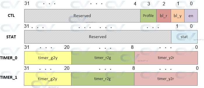
This is not a complete design since our purpose is simply to show how registers in this design can be read/written using a UVM register model. All the signals listed as the module ports belong to APB specification.
module traffic (  input          pclk,
                  input          presetn,
                  input [31:0]   paddr,
                  input [31:0]   pwdata,
                  input          psel,
                  input          pwrite,
                  input          penable,

                  // Outputs
                  output [31:0]  prdata);

   reg [3:0]      ctl_reg;    // profile, blink_red, blink_yellow, mod_en RW
   reg [1:0]      stat_reg;   // state[1:0]
   reg [31:0]     timer_0;    // timer_g2y[31:20], timer_r2g[19:8], timer_y2r[7:0] RW
   reg [31:0]     timer_1;    // timer_g2y[31:20], timer_r2g[19:8], timer_y2r[7:0] RW

   reg [31:0]     data_in;
   reg [31:0]     rdata_tmp;

   // Set all registers to default values
   always @ (posedge pclk) begin
      if (!presetn) begin
         data_in <= 0;
         ctl_reg  <= 0;
         stat_reg <= 0;
         timer_0  <= 32'hcafe_1234;
         timer_1  <= 32'hface_5678;
      end
   end

   // Capture write data
   always @ (posedge pclk) begin
      if (presetn & psel & penable)
         if (pwrite)
            case (paddr)
               'h0   : ctl_reg <= pwdata;
               'h4   : timer_0 <= pwdata;
               'h8   : timer_1 <= pwdata;
               'hc   : stat_reg <= pwdata;
            endcase
   end

   // Provide read data
   always @ (penable) begin
      if (psel & !pwrite)
         case (paddr)
            'h0 : rdata_tmp <= ctl_reg;
            'h4 : rdata_tmp <= timer_0;
            'h8 : rdata_tmp <= timer_1;
            'hc : rdata_tmp <= stat_reg;
         endcase
   end

   assign prdata = (psel & penable & !pwrite) ? rdata_tmp : 'hz;

endmodule
Interface
Let us declare an interface with signals in the APB protocol and this interface can be passed to the testbench as a virtual interface for the driver to drive some values to the design. To keep things simple, let us not declare clocking blocks and modports, although they are recommended in a real project.
interface bus_if (input pclk);
   logic [31:0]   paddr;
   logic [31:0]   pwdata;
   logic [31:0]   prdata;
   logic          pwrite;
   logic          psel;
   logic          penable;
   logic          presetn;
endinterface
2-state Data Types
The 2-state data types, such as bit and int, can only represent two values: 0 and 1. This simplification reduces memory usage during simulation, as each bit requires only one bit of storage instead of two bits needed for the 4-state types (which include 0, 1, X for unknown, and Z for high impedance). This leads to faster simulation performance due to lower memory overhead and reduced complexity in handling states.
