uvm_driver is a child of uvm_component that has a TLM port to communicate with the sequencer. The driver is a parameterized class with the type of request and response sequence items. This allows the driver to send back a different sequence_item type back to the sequencer as the response. However, most drivers use a response object of the same type as the request sequence item.
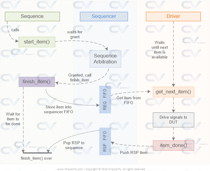
The uvm_driver gets request sequence items (REQ) from the sequencer FIFO using a handshake mechanism and optionally returns a response sequence item (RSP) back to the sequencer response FIFO. There are primarily two ways for the driver to get a sequence item from the sequencer. In this article, we'll look at an example that uses the first style.
Using get_next_item method in a driver
In this case, the driver requests for a sequence item from the sequencer using the get_next_item method through the seq_item_port TLM handle. Since the implementation of this port is defined in the sequencer, the function call makes the sequencer to pop an item from its internal FIFO and provide it to the driver via the argument provided in get_next_item method.
class my_driver extends uvm_driver #(my_data);
	`uvm_component_utils (my_driver)

   virtual task run_phase(uvm_phase phase);
      super.run_phase(phase);

      // 1. This task will get an item from the sequencer using get_next_item()
      `uvm_info ("DRIVER", $sformatf ("Waiting for data from sequencer"), UVM_MEDIUM)
      seq_item_port.get_next_item(req);

      // 2. For simplicity, lets just assume the driver drives the received packet
      // during this time and consumes 20ns to complete driving the transaction
      `uvm_info ("DRIVER", $sformatf ("Start driving tx addr=0x%0h data=0x%0h", req.addr, req.data), UVM_MEDIUM)
      #20;

      // 3. After driver has finished the transaction, it has to let the sequencer know
      // by calling item_done()
      `uvm_info ("DRIVER", $sformatf ("Finish driving tx addr=0x%0h data=0x%0h", req.addr, req.data), UVM_MEDIUM)
      seq_item_port.item_done();
   endtask
Once driver gets the next item, it can drive the data in the received sequence item to the DUT via a virtual interface handle. After the driver has finished driving the item, it has to let the sequencer know that the process has finished using item_done method.
How does the sequencer get these sequence items ?
A uvm_sequence is started on a sequencer which pushes the sequence item onto the sequencer's FIFO.
class my_sequence extends uvm_sequence;
	`uvm_object_utils (my_sequence)


  virtual task body();
  	// 1. Create an item the connected sequencer can accept
    my_data tx = my_data::type_id::create("tx");
    `uvm_info ("SEQ", $sformatf("About to call start_item"), UVM_MEDIUM)

    // 2. Call the start_item() task which will send this object to the driver
    start_item(tx);
    `uvm_info ("SEQ", $sformatf("start_item() fn call done"), UVM_MEDIUM)

    // 3. Because the class handle passed to the driver points to the same object, we
    // can do late randomization
    tx.randomize();
    `uvm_info ("SEQ", $sformatf("tx randomized with addr=0x%0h data=0x%0h", tx.addr, tx.data), UVM_MEDIUM)

    // 4. Call finish_item method so that the sequence waits until the driver lets the
    // sequencer know that this item has finished
    finish_item(tx);
    `uvm_info ("SEQ", $sformatf("finish_item() fn call done"), UVM_MEDIUM)
  endtask
endclass
Example
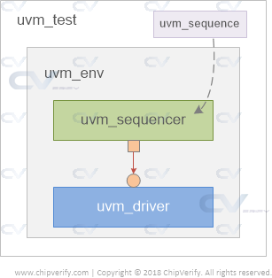
To illustrate how the get and put method calls between driver and sequencer work, let us build a simple testbench structure like the one shown below.
Define a sequence item
To keep things simple, let us define a transaction object class that will become the sequence item used for sequencer-driver communication. Assume that this sequence item contains two variables called addr and data.
// Note that this class is dervide from "uvm_sequence_item"
class my_data extends uvm_sequence_item;
  rand bit [7:0]   data;
  rand bit [7:0]   addr;

	// Rest of the class contents come here ...
endclass
Define the driver
The uvm_driver is parameterized to accept a class object of the type my_data and the driver is expected to unpack this class object and drive the signals appropriately to the DUT via the interface.
class my_driver extends uvm_driver #(my_data);
   `uvm_component_utils (my_driver)
   // Other parts of the driver code if they exist

   virtual task run_phase(uvm_phase phase);
      super.run_phase(phase);

      // 1. Get the next available item from the sequencer. If none exists, then wait until
      // next item is available -> this is blocking in nature
      `uvm_info ("DRIVER", $sformatf ("Waiting for data from sequencer"), UVM_MEDIUM)
      seq_item_port.get_next_item(req);

      // 2. Let us assume that the driver actively does the pin wiggling of the DUT during this time and
      // consider it takes 20ns
      `uvm_info ("DRIVER", $sformatf ("Start driving tx addr=0x%0h data=0x%0h", req.addr, req.data), UVM_MEDIUM)
      #20;

      // 3. After the driver has driven all data to the DUT, it should let the sequencer know that it finished
      // driving the transaction by calling "item_done". Optionally the response packet can be passed along with
      // the item_done method call and it will be placed in the sequencer's response FIFO
      `uvm_info ("DRIVER", $sformatf ("Finish driving tx addr=0x%0h data=0x%0h", req.addr, req.data), UVM_MEDIUM)
      seq_item_port.item_done();
   endtask
endclass
Define the sequence
A sequence item is always started using the start_item and finish_item methods.
class my_sequence extends uvm_sequence #(my_data);
  	// Rest of the sequence code

  	virtual task body();
  		// 1. Create a sequence item of the given type
    	my_data tx = my_data::type_id::create("tx");
    	`uvm_info ("SEQ", $sformatf("About to call start_item"), UVM_MEDIUM)

    	// 2. Start the item on the sequencer which will send this to the driver
    	start_item(tx);
    	`uvm_info ("SEQ", $sformatf("start_item() fn call done"), UVM_MEDIUM)

    	// 3. Do some late randomization to create a different content in this transaction object
    	tx.randomize();
    	`uvm_info ("SEQ", $sformatf("tx randomized with addr=0x%0h data=0x%0h", tx.addr, tx.data), UVM_MEDIUM)

    	// 4. Call finish_item to let driver continue driving the transaction object or sequence item
    	finish_item(tx);
    	`uvm_info ("SEQ", $sformatf("finish_item() fn call done"), UVM_MEDIUM)
  	endtask
endclass
Define the test class
To keep things simple, let us directly create instances of the driver and sequencer inside the test class.
Driver and Sequencer should be instantiated inside an agent. An agent is instantiated in an environment and the the environment in turn should be created in the test.
class base_test extends uvm_test;
	// Rest of the test code is here

	// The sequencer is parameterized to accept objects of type "my_data" only
  	my_driver                	m_drv0;
  	uvm_sequencer #(my_data) 	m_seqr0;
  	my_sequence   				m_seq;

	// Build the sequencer and driver components
  	virtual function void build_phase(uvm_phase phase);
     	super.build_phase(phase);
     	m_drv0 = my_driver::type_id::create ("m_drv0", this);
     	m_seqr0 = uvm_sequencer#(my_data)::type_id::create ("m_seqr0", this);
  	endfunction

   	// Connect the sequencer "export" to the driver's "port"
   	virtual function void connect_phase (uvm_phase phase);
     	super.connect_phase (phase);
     	m_drv0.seq_item_port.connect (m_seqr0.seq_item_export);
   	endfunction

	// Start the sequence on the given sequencer
  	virtual task run_phase(uvm_phase phase);
    	m_seq = my_sequence::type_id::create("m_seq");
    	phase.raise_objection(this);
    	m_seq.start(m_seqr0);
    	phase.drop_objection(this);
  	endtask
endclass
UVM_INFO @ 0: reporter [RNTST] Running test base_test...
UVM_INFO testbench.sv(33) @ 0: uvm_test_top.m_top_env.m_drv0 [DRIVER] Waiting for data from sequencer
UVM_INFO testbench.sv(71) @ 0: uvm_test_top.m_top_env.m_seqr0@@m_seq [SEQ] About to call start_item
UVM_INFO testbench.sv(73) @ 0: uvm_test_top.m_top_env.m_seqr0@@m_seq [SEQ] start_item() fn call done
UVM_INFO testbench.sv(75) @ 0: uvm_test_top.m_top_env.m_seqr0@@m_seq [SEQ] tx randomized with addr=0x8f data=0x1d
UVM_INFO testbench.sv(35) @ 0: uvm_test_top.m_top_env.m_drv0 [DRIVER] Start driving tx addr=0x8f data=0x1d
UVM_INFO testbench.sv(37) @ 20: uvm_test_top.m_top_env.m_drv0 [DRIVER] Finish driving tx addr=0x8f data=0x1d
UVM_INFO testbench.sv(77) @ 20: uvm_test_top.m_top_env.m_seqr0@@m_seq [SEQ] finish_item() fn call done
UVM_INFO /playground_lib/uvm-1.2/src/base/uvm_objection.svh(1271) @ 20: reporter [TEST_DONE] 'run' phase is ready to proceed to the 'extract' phase
UVM_INFO /playground_lib/uvm-1.2/src/base/uvm_report_server.svh(847) @ 20: reporter [UVM/REPORT/SERVER]
--- UVM Report Summary ---
Some of the main built-in primitives were discussed in the previous article and it would be good to see some practical examples of using simple and, nor and not gates.
Note that in order to write the Verilog code using gates, it is necessary for you to know how to connect the elements. This is very different from a behavioral description in which case the selection and connection of elements is left upto the synthesis tools.
Example #1: 2x1 Multiplexer
Output of module has to be of type wire in order to connect with the output port of a primitive.
module mux_2x1 ( input a, b, sel,
				 output out);
	wire sel_n;
	wire out_0;

	not (sel_n, sel);

	and (out_0, a, sel);
	and (out_1, b, sel_n);

	or (out, out_0, out_1);
endmodule
module tb;
  reg a, b, sel;
  wire out;
  integer i;

  mux_2x1 u0 ( 	.a(a), .b(b), .sel(sel), .out(out));

  initial begin
    {a, b, sel} <= 0;

    $monitor ("T=%0t a=%0b b=%0b sel=%0b out=%0b", $time, a, b, sel, out);

	for (int i = 0; i < 10; i = i+1) begin
    	#1 	a <= $random;
      		b <= $random;
			sel <= $random;
    end
  end
endmodule
ncsim> run
T=0 a=0 b=0 sel=0 out=0
T=1 a=0 b=1 sel=1 out=0
T=2 a=1 b=1 sel=1 out=1
T=3 a=1 b=0 sel=1 out=1
T=6 a=0 b=1 sel=0 out=1
T=7 a=1 b=1 sel=0 out=1
T=8 a=1 b=0 sel=0 out=0
T=9 a=0 b=1 sel=0 out=1
T=10 a=1 b=1 sel=1 out=1
ncsim: *W,RNQUIE: Simulation is complete.
Full Adder
module fa (	input a, b, cin,
			output sum, cout);

	wire s1, net1, net2;

	xor (s1, a, b);
	and (net1, a, b);

	xor (sum, s1, cin);
	and (net2, s1, cin);

	xor (cout, net1, net2);

endmodule
module tb;
  reg a, b, cin;
  wire sum, cout;
  integer i;

  fa u0 ( .a(a), .b(b), .cin(cin),
         .sum(sum), .cout(cout));

  initial begin
    {a, b, cin} <= 0;

    $monitor ("T=%0t a=%0b b=%0b cin=%0b cout=%0b sum=%0b",
              $time, a, b, cin, cout, sum);

    for (i = 0; i < 10; i = i+1) begin
      #1 	a <= $random;
      		b <= $random;
      		cin <= $random;
    end
  end
endmodule
ncsim> run
T=0 a=0 b=0 cin=0 cout=0 sum=0
T=1 a=0 b=1 cin=1 cout=1 sum=0
T=2 a=1 b=1 cin=1 cout=1 sum=1
T=3 a=1 b=0 cin=1 cout=1 sum=0
T=6 a=0 b=1 cin=0 cout=0 sum=1
T=7 a=1 b=1 cin=0 cout=1 sum=0
T=8 a=1 b=0 cin=0 cout=0 sum=1
T=9 a=0 b=1 cin=0 cout=0 sum=1
T=10 a=1 b=1 cin=1 cout=1 sum=1
ncsim: *W,RNQUIE: Simulation is complete.
2x4 Decoder
module tb;
  reg x, y, en;
  wire a, b, c, d;
  integer i;

  dec_2x4 u0 ( .x(x), .y(y), .en(en),
           		.a(a), .b(b), .c(c), .d(d));

  initial begin
    {x, y, en} <= 0;
    $monitor ("T=%0t x=%0b y=%0b en=%0b a=%0b b=%0b c=%0b d=%0b",
              $time, x, y, en, a, b, c, d);

	en <= 1;
    for (i = 0; i < 10; i = i+1) begin
      #1 	x <= $random;
      		y <= $random;
    end
  end
endmodule
ncsim> run
T=0 x=0 y=0 en=1 a=0 b=0 c=0 d=1
T=1 x=0 y=1 en=1 a=0 b=0 c=1 d=0
T=2 x=1 y=1 en=1 a=1 b=0 c=0 d=0
T=4 x=1 y=0 en=1 a=0 b=1 c=0 d=0
T=5 x=1 y=1 en=1 a=1 b=0 c=0 d=0
T=6 x=0 y=1 en=1 a=0 b=0 c=1 d=0
T=7 x=1 y=0 en=1 a=0 b=1 c=0 d=0
T=10 x=1 y=1 en=1 a=1 b=0 c=0 d=0
ncsim: *W,RNQUIE: Simulation is complete.
4x2 Encoder
module enc_4x2 ( input a, b, c, d,
                output x, y);

  or (x, b, d);
  or (y, c, d);

endmodule
module tb;
  reg a, b, c, d;
  wire x, y;
  integer i;

  enc_4x2 u0 ( .a(a), .b(b), .c(c), .d(d), .x(x), .y(y));

  initial begin
    {a, b, c, d} <= 0;

    $monitor("T=%0t a=%0b b=%0b c=%0b d=%0b x=%0b y=%0b",
             $time, a, b, c, d, x, y);

    for (i = 0; i <= 16; i = i+1) begin
      #1 {a, b, c, d} <= i;
    end
  end

endmodule
ncsim> run
T=0 a=0 b=0 c=0 d=0 x=0 y=0
T=2 a=0 b=0 c=0 d=1 x=1 y=1
T=3 a=0 b=0 c=1 d=0 x=0 y=1
T=4 a=0 b=0 c=1 d=1 x=1 y=1
T=5 a=0 b=1 c=0 d=0 x=1 y=0
T=6 a=0 b=1 c=0 d=1 x=1 y=1
T=7 a=0 b=1 c=1 d=0 x=1 y=1
T=8 a=0 b=1 c=1 d=1 x=1 y=1
T=9 a=1 b=0 c=0 d=0 x=0 y=0
T=10 a=1 b=0 c=0 d=1 x=1 y=1
T=11 a=1 b=0 c=1 d=0 x=0 y=1
T=12 a=1 b=0 c=1 d=1 x=1 y=1
T=13 a=1 b=1 c=0 d=0 x=1 y=0
T=14 a=1 b=1 c=0 d=1 x=1 y=1
T=15 a=1 b=1 c=1 d=0 x=1 y=1
T=16 a=1 b=1 c=1 d=1 x=1 y=1
T=17 a=0 b=0 c=0 d=0 x=0 y=0
ncsim: *W,RNQUIE: Simulation is complete.
There are two types of arrays in SystemVerilog - packed and unpacked arrays.
A packed array is used to refer to dimensions declared before the variable name.
	bit [3:0] 	data; 			// Packed array or vector
	logic 		queue [9:0]; 	// Unpacked array
A packed array is guaranteed to be represented as a contiguous set of bits. They can be made of only the single bit data types like bit, logic, and other recursively packed arrays.
Single Dimensional Packed Arrays
A one-dimensional packed array is also called as a vector.
module tb;
	bit [7:0] 	m_data; 	// A vector or 1D packed array

	initial begin
		// 1. Assign a value to the vector
		m_data = 8'hA2;

		// 2. Iterate through each bit of the vector and print value
		for (int i = 0; i < $size(m_data); i++) begin
			$display ("m_data[%0d] = %b", i, m_data[i]);
		end
	end
endmodule
ncsim> run
m_data[0] = 0
m_data[1] = 1
m_data[2] = 0
m_data[3] = 0
m_data[4] = 0
m_data[5] = 1
m_data[6] = 0
m_data[7] = 1
ncsim: *W,RNQUIE: Simulation is complete.
Multidimensional Packed Arrays
A multidimensional packed array is still a set of contiguous bits but are also segmented into smaller groups.
Example #1
The code shown below declares a 2D packed array that occupies 32-bits or 4 bytes and iterates through the segments and prints its value.
module tb;
  bit [3:0][7:0] 	m_data; 	// A MDA, 4 bytes

	initial begin
		// 1. Assign a value to the MDA
		m_data = 32'hface_cafe;

      $display ("m_data = 0x%0h", m_data);

		// 2. Iterate through each segment of the MDA and print value
      for (int i = 0; i < $size(m_data); i++) begin
        $display ("m_data[%0d] = %b (0x%0h)", i, m_data[i], m_data[i]);
		end
	end
endmodule
ncsim> run
m_data = 0xfacecafe
m_data[0] = 11111110 (0xfe)
m_data[1] = 11001010 (0xca)
m_data[2] = 11001110 (0xce)
m_data[3] = 11111010 (0xfa)
ncsim: *W,RNQUIE: Simulation is complete.
Example #2
Let us see a 3D packed array now.
module tb;
  bit [2:0][3:0][7:0] 	m_data; 	// An MDA, 12 bytes

	initial begin
		// 1. Assign a value to the MDA
      m_data[0] = 32'hface_cafe;
      m_data[1] = 32'h1234_5678;
      m_data[2] = 32'hc0de_fade;

      // m_data gets a packed value
      $display ("m_data = 0x%0h", m_data);

		// 2. Iterate through each segment of the MDA and print value
      foreach (m_data[i]) begin
        $display ("m_data[%0d] = 0x%0h", i, m_data[i]);
        foreach (m_data[i][j]) begin
          $display ("m_data[%0d][%0d] = 0x%0h", i, j, m_data[i][j]);
        end
      end
	end
endmodule
ncsim> run
m_data = 0xc0defade12345678facecafe
m_data[2] = 0xc0defade
m_data[2][3] = 0xc0
m_data[2][2] = 0xde
m_data[2][1] = 0xfa
m_data[2][0] = 0xde
m_data[1] = 0x12345678
m_data[1][3] = 0x12
m_data[1][2] = 0x34
m_data[1][1] = 0x56
m_data[1][0] = 0x78
m_data[0] = 0xfacecafe
m_data[0][3] = 0xfa
m_data[0][2] = 0xce
m_data[0][1] = 0xca
m_data[0][0] = 0xfe
ncsim: *W,RNQUIE: Simulation is complete.
A generate block allows to multiply module instances or perform conditional instantiation of any module. It provides the ability for the design to be built based on Verilog parameters. These statements are particularly convenient when the same operation or module instance needs to be repeated multiple times or if certain code has to be conditionally included based on given Verilog parameters.
A generate block cannot contain port, parameter, specparam declarations or specify blocks. However, other module items and other generate blocks are allowed. All generate instantiations are coded within a module and between the keywords generate and endgenerate.
Generated instantiations can have either modules, continuous assignments, always or initial blocks and user defined primitives. There are two types of generate constructs - loops and conditionals.
Generate for loop
A half adder will be instantiated N times in another top level design module called my_design using a generate for loop construct. The loop variable has to be declared using the keyword genvar which tells the tool that this variable is to be specifically used during elaboration of the generate block.
// Design for a half-adder
module ha ( input   a, b,
            output  sum, cout);

  assign sum  = a ^ b;
  assign cout = a & b;
endmodule

// A top level design that contains N instances of half adder
module my_design
	#(parameter N=4)
		(	input [N-1:0] a, b,
			output [N-1:0] sum, cout);

	// Declare a temporary loop variable to be used during
	// generation and won't be available during simulation
	genvar i;

	// Generate for loop to instantiate N times
	generate
		for (i = 0; i < N; i = i + 1) begin
          ha u0 (a[i], b[i], sum[i], cout[i]);
		end
	endgenerate
endmodule
Testbench
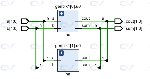
The testbench parameter is used to control the number of half adder instances in the design. When N is 2, my_design will have two instances of half adder.
module tb;
	parameter N = 2;
  reg  [N-1:0] a, b;
  wire [N-1:0] sum, cout;

  // Instantiate top level design with N=2 so that it will have 2
  // separate instances of half adders and both are given two separate
  // inputs
  my_design #(.N(N)) md( .a(a), .b(b), .sum(sum), .cout(cout));

  initial begin
    a <= 0;
    b <= 0;

    $monitor ("a=0x%0h b=0x%0h sum=0x%0h cout=0x%0h", a, b, sum, cout);

    #10 a <= 'h2;
    		b <= 'h3;
    #20 b <= 'h4;
    #10 a <= 'h5;
  end
endmodule
a[0] and b[0] gives the output sum[0] and cout[0] while a[1] and b[1] gives the output sum[1] and cout[1] .
ncsim> run
a=0x0 b=0x0 sum=0x0 cout=0x0
a=0x2 b=0x3 sum=0x1 cout=0x2
a=0x2 b=0x0 sum=0x2 cout=0x0
a=0x1 b=0x0 sum=0x1 cout=0x0
ncsim: *W,RNQUIE: Simulation is complete.
ncsim> exit
See that elaborated RTL does indeed have two half adder instances generated by the generate block.
Generate if
Shown below is an example using an if else inside a generate construct to select between two different multiplexer implementations. The first design uses an assign statement to implement a mux while the second design uses a case statement. A parameter called USE_CASE is defined in the top level design module to select between the two choices.
// Design #1: Multiplexer design uses an "assign" statement to assign
// out signal
module mux_assign ( input a, b, sel,
                   output out);
  assign out = sel ? a : b;

  // The initial display statement is used so that
  // we know which design got instantiated from simulation
  // logs
  initial
  	$display ("mux_assign is instantiated");
endmodule

// Design #2: Multiplexer design uses a "case" statement to drive
// out signal
module mux_case (input a, b, sel,
                 output reg out);
  always @ (a or b or sel) begin
  	case (sel)
    	0 : out = a;
   	 	1 : out = b;
  	endcase
  end

  // The initial display statement is used so that
  // we know which design got instantiated from simulation
  // logs
  initial
    $display ("mux_case is instantiated");
endmodule

// Top Level Design: Use a parameter to choose either one
module my_design (	input a, b, sel,
         			output out);
  parameter USE_CASE = 0;

  // Use a "generate" block to instantiate either mux_case
  // or mux_assign using an if else construct with generate
  generate
  	if (USE_CASE)
      mux_case mc (.a(a), .b(b), .sel(sel), .out(out));
    else
      mux_assign ma (.a(a), .b(b), .sel(sel), .out(out));
  endgenerate

endmodule
Testbench
Testbench instantiates the top level module my_design and sets the parameter USE_CASE to 1 so that it instantiates the design using case statement.
module tb;
	// Declare testbench variables
  reg a, b, sel;
  wire out;
  integer i;

  // Instantiate top level design and set USE_CASE parameter to 1 so that
  // the design using case statement is instantiated
  my_design #(.USE_CASE(1)) u0 ( .a(a), .b(b), .sel(sel), .out(out));

  initial begin
  	// Initialize testbench variables
  	a <= 0;
    b <= 0;
    sel <= 0;

    // Assign random values to DUT inputs with some delay
    for (i = 0; i < 5; i = i + 1) begin
      #10 a <= $random;
      	  b <= $random;
          sel <= $random;
      $display ("i=%0d a=0x%0h b=0x%0h sel=0x%0h out=0x%0h", i, a, b, sel, out);
    end
  end
endmodule
When the parameter USE_CASE is 1, it can be seen from the simulation log that the multiplexer design using case statement is instantiated. And when USE_CASE is zero, the multiplexer design using assign statement is instantiated. This is visible from the display statement that gets printed in the simulation log.
// When USE_CASE = 1
ncsim> run
mux_case is instantiated
i=0 a=0x0 b=0x0 sel=0x0 out=0x0
i=1 a=0x0 b=0x1 sel=0x1 out=0x1
i=2 a=0x1 b=0x1 sel=0x1 out=0x1
i=3 a=0x1 b=0x0 sel=0x1 out=0x0
i=4 a=0x1 b=0x0 sel=0x1 out=0x0
ncsim: *W,RNQUIE: Simulation is complete.

// When USE_CASE = 0
ncsim> run
mux_assign is instantiated
i=0 a=0x0 b=0x0 sel=0x0 out=0x0
i=1 a=0x0 b=0x1 sel=0x1 out=0x0
i=2 a=0x1 b=0x1 sel=0x1 out=0x1
i=3 a=0x1 b=0x0 sel=0x1 out=0x1
i=4 a=0x1 b=0x0 sel=0x1 out=0x1
ncsim: *W,RNQUIE: Simulation is complete.
Generate Case
A generate case allows modules, initial and always blocks to be instantiated in another module based on a case expression to select one of the many choices.
// Design #1: Half adder
module ha (input a, b,
           output reg sum, cout);
  always @ (a or b)
  {cout, sum} = a + b;

  initial
    $display ("Half adder instantiation");
endmodule

// Design #2: Full adder
module fa (input a, b, cin,
           output reg sum, cout);
  always @ (a or b or cin)
  {cout, sum} = a + b + cin;

    initial
      $display ("Full adder instantiation");
endmodule

// Top level design: Choose between half adder and full adder
module my_adder (input a, b, cin,
                 output sum, cout);
  parameter ADDER_TYPE = 1;

  generate
    case(ADDER_TYPE)
      0 : ha u0 (.a(a), .b(b), .sum(sum), .cout(cout));
      1 : fa u1 (.a(a), .b(b), .cin(cin), .sum(sum), .cout(cout));
    endcase
  endgenerate
endmodule
Testbench
module tb;
  reg a, b, cin;
  wire sum, cout;

  my_adder #(.ADDER_TYPE(0)) u0 (.a(a), .b(b), .cin(cin), .sum(sum), .cout(cout));

  initial begin
    a <= 0;
    b <= 0;
    cin <= 0;

    $monitor("a=0x%0h b=0x%0h cin=0x%0h cout=0%0h sum=0x%0h",
             a, b, cin, cout, sum);

    for (int i = 0; i < 5; i = i + 1) begin
      #10 a <= $random;
      b <= $random;
      cin <= $random;
    end
  end
endmodule
Note that because a half adder is instantiated, cin does not have any effect on the outputs sum and cout .
ncsim> run
Half adder instantiation
a=0x0 b=0x0 cin=0x0 cout=00 sum=0x0
a=0x0 b=0x1 cin=0x1 cout=00 sum=0x1
a=0x1 b=0x1 cin=0x1 cout=01 sum=0x0
a=0x1 b=0x0 cin=0x1 cout=00 sum=0x1
ncsim: *W,RNQUIE: Simulation is complete.
The verilog always block can be used for both sequential and combinational logic. A few design examples were shown using an assign statement in a previous article. The same set of designs will be explored next using an always block.
Example #1 : Simple combinational logic
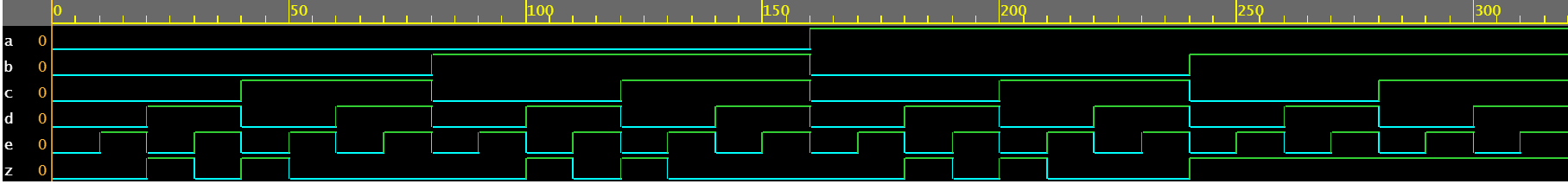
The code shown below implements a simple digital combinational logic which has an output signal called z of type reg that gets updated whenever one of the signals in the sensitivity list changes its value. The sensitivity list is declared within parentheses after the @ operator.
module combo ( 	input 	a, b, c, d, e,
								output 	reg z);

	always @ ( a or b or c or d or e) begin
		z = ((a & b) | (c ^ d) & ~e);
	end

endmodule
The module combo gets elaborated into the following hardware schematic using synthesis tools and can be seen that the combinational logic is implemented with digital gates.
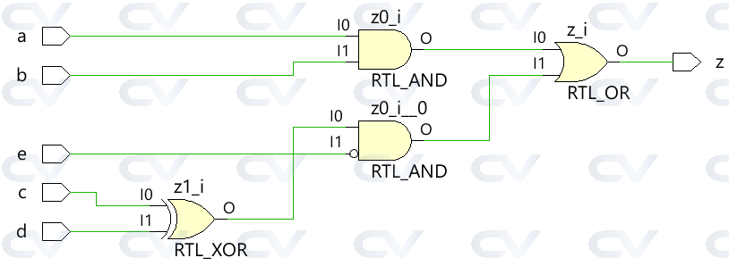
 Use blocking assigments when modeling combinational logic with an always block
Testbench
The testbench is a platform for simulating the design to ensure that the design does behave as expected. All combinations of inputs are driven to the design module using a for loop with a delay statement of 10 time units so that the new value is applied to the inputs after some time.
module tb;
	// Declare testbench variables
  reg a, b, c, d, e;
  wire z;
  integer i;

  // Instantiate the design and connect design inputs/outputs with
  // testbench variables
  combo u0 ( .a(a), .b(b), .c(c), .d(d), .e(e), .z(z));

  initial begin
  	// At the beginning of time, initialize all inputs of the design
  	// to a known value, in this case we have chosen it to be 0.
    a <= 0;
    b <= 0;
    c <= 0;
    d <= 0;
    e <= 0;

    // Use a $monitor task to print any change in the signal to
    // simulation console
    $monitor ("a=%0b b=%0b c=%0b d=%0b e=%0b z=%0b",
              a, b, c, d, e, z);

    // Because there are 5 inputs, there can be 32 different input combinations
    // So use an iterator "i" to increment from 0 to 32 and assign the value
    // to testbench variables so that it drives the design inputs
    for (i = 0; i < 32; i = i + 1) begin
      {a, b, c, d, e} = i;
      #10;
    end
  end
endmodule
ncsim> run
a=0 b=0 c=0 d=0 e=0 z=0
a=0 b=0 c=0 d=0 e=1 z=0
a=0 b=0 c=0 d=1 e=0 z=1
a=0 b=0 c=0 d=1 e=1 z=0
a=0 b=0 c=1 d=0 e=0 z=1
a=0 b=0 c=1 d=0 e=1 z=0
a=0 b=0 c=1 d=1 e=0 z=0
a=0 b=0 c=1 d=1 e=1 z=0
a=0 b=1 c=0 d=0 e=0 z=0
a=0 b=1 c=0 d=0 e=1 z=0
a=0 b=1 c=0 d=1 e=0 z=1
a=0 b=1 c=0 d=1 e=1 z=0
a=0 b=1 c=1 d=0 e=0 z=1
a=0 b=1 c=1 d=0 e=1 z=0
a=0 b=1 c=1 d=1 e=0 z=0
a=0 b=1 c=1 d=1 e=1 z=0
a=1 b=0 c=0 d=0 e=0 z=0
a=1 b=0 c=0 d=0 e=1 z=0
a=1 b=0 c=0 d=1 e=0 z=1
a=1 b=0 c=0 d=1 e=1 z=0
a=1 b=0 c=1 d=0 e=0 z=1
a=1 b=0 c=1 d=0 e=1 z=0
a=1 b=0 c=1 d=1 e=0 z=0
a=1 b=0 c=1 d=1 e=1 z=0
a=1 b=1 c=0 d=0 e=0 z=1
a=1 b=1 c=0 d=0 e=1 z=1
a=1 b=1 c=0 d=1 e=0 z=1
a=1 b=1 c=0 d=1 e=1 z=1
a=1 b=1 c=1 d=0 e=0 z=1
a=1 b=1 c=1 d=0 e=1 z=1
a=1 b=1 c=1 d=1 e=0 z=1
a=1 b=1 c=1 d=1 e=1 z=1
ncsim: *W,RNQUIE: Simulation is complete.
Note that both methods, assign and always, get implemented into the same hardware logic.
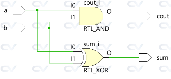
Example #2: Half Adder
The half adder module accepts two scalar inputs a and b and uses combinational logic to assign the output signals sum and carry bit cout . The sum is driven by an XOR between a and b while the carry bit is obtained by an AND between the two inputs.
module ha ( input 	a, b,
						output	sum, cout);

	always @ (a or b) begin
		{cout, sum} = a + b;
	end

endmodule
Testbench
module tb;
	// Declare testbench variables
  reg a, b;
  wire sum, cout;
  integer i;

  // Instantiate the design and connect design inputs/outputs with
  // testbench variables
  ha u0 ( .a(a), .b(b), .sum(sum), .cout(cout));

  initial begin
  	// At the beginning of time, initialize all inputs of the design
  	// to a known value, in this case we have chosen it to be 0.
    a <= 0;
    b <= 0;

    // Use a $monitor task to print any change in the signal to
    // simulation console
    $monitor("a=%0b b=%0b sum=%0b cout=%0b", a, b, sum, cout);

    // Because there are only 2 inputs, there can be 4 different input combinations
    // So use an iterator "i" to increment from 0 to 4 and assign the value
    // to testbench variables so that it drives the design inputs
    for (i = 0; i < 4; i = i + 1) begin
      {a, b} = i;
      #10;
    end
  end
endmodule
ncsim> run
a=0 b=0 sum=0 cout=0
a=0 b=1 sum=1 cout=0
a=1 b=0 sum=1 cout=0
a=1 b=1 sum=0 cout=1
ncsim: *W,RNQUIE: Simulation is complete.

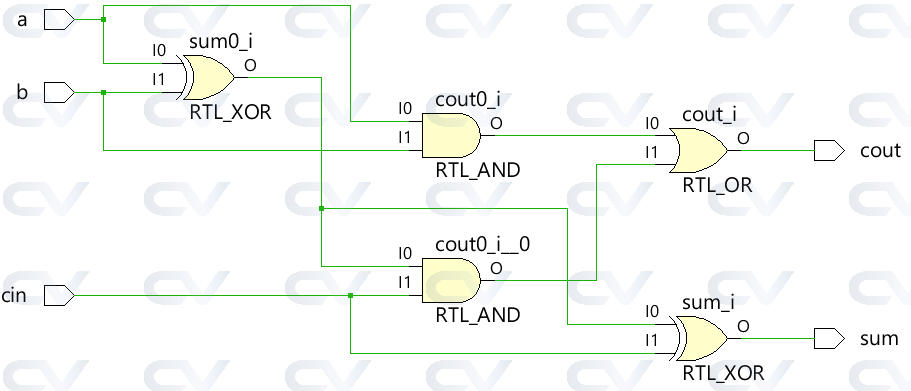
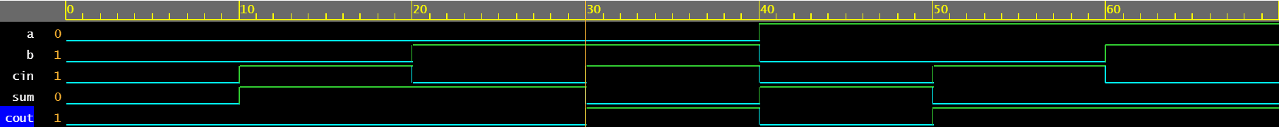
Example #3: Full Adder
An always block can be used to describe the behavior of a full adder to drive the outputs sum and cout .
module fa (	input 	a, b, cin,
			output reg	sum, cout);

  always @ (a or b or cin) begin
    {cout, sum} = a + b + cin;
  end

endmodule
Testbench
module tb;
  reg a, b, cin;
  wire sum, cout;
  integer i;

  fa u0 ( .a(a), .b(b), .cin(cin), .sum(sum), .cout(cout));

  initial begin
    a <= 0;
    b <= 0;

    $monitor("a=%0b b=%0b cin=%0b cout=%0b sum=%0b", a, b, cin, cout, sum);

    for (i = 0; i < 8; i = i + 1) begin
      {a, b, cin} = i;
      #10;
    end
  end
endmodule
ncsim> run
a=0 b=0 cin=0 cout=0 sum=0
a=0 b=0 cin=1 cout=0 sum=1
a=0 b=1 cin=0 cout=0 sum=1
a=0 b=1 cin=1 cout=1 sum=0
a=1 b=0 cin=0 cout=0 sum=1
a=1 b=0 cin=1 cout=1 sum=0
a=1 b=1 cin=0 cout=1 sum=0
a=1 b=1 cin=1 cout=1 sum=1
ncsim: *W,RNQUIE: Simulation is complete.
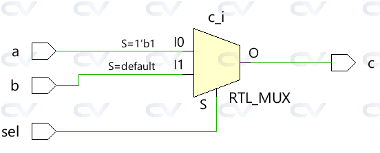
Example #4: 2x1 Multiplexer
The simple 2x1 multiplexer uses a ternary operator to decide which input should be assigned to the output c . If sel is 1, output is driven by a and if sel is 0 output is driven by b .
module mux_2x1 (input 	a, b, sel,
				output 	reg c);


  always @ ( a or b or sel) begin
	c = sel ? a : b;
  end
endmodule
Testbench
module tb;
	// Declare testbench variables
  reg a, b, sel;
  wire c;
  integer i;

  // Instantiate the design and connect design inputs/outputs with
  // testbench variables
  mux_2x1 u0 ( .a(a), .b(b), .sel(sel), .c(c));

  initial begin
  	// At the beginning of time, initialize all inputs of the design
  	// to a known value, in this case we have chosen it to be 0.
    a <= 0;
    b <= 0;
    sel <= 0;

    $monitor("a=%0b b=%0b sel=%0b c=%0b", a, b, sel, c);

    for (i = 0; i < 3; i = i + 1) begin
      {a, b, sel} = i;
      #10;
    end
  end
endmodule
ncsim> run
a=0 b=0 sel=0 c=0
a=0 b=0 sel=1 c=0
a=0 b=1 sel=0 c=1
ncsim: *W,RNQUIE: Simulation is complete.

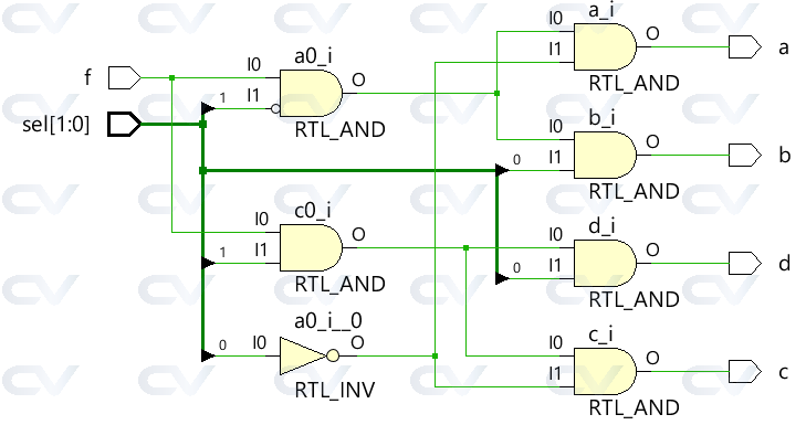
Example #5: 1x4 Demultiplexer
The demultiplexer uses a combination of sel and f inputs to drive the different output signals. Each output signal is of type reg and used inside an always block that gets updated based on changes in the signals listed in the sensitivity list.
module demux_1x4 (	input 				f,
										input [1:0]	 	sel,
										output reg		a, b, c, d);

  always @ ( f or sel) begin
    a = f & ~sel[1] & ~sel[0];
    b = f &  sel[1] & ~sel[0];
    c = f & ~sel[1] &  sel[0];
    d = f &  sel[1] &  sel[0];
  end

endmodule
Testbench
module tb;
	// Declare testbench variables
  reg f;
  reg [1:0] sel;
  wire a, b, c, d;
  integer i;

  // Instantiate the design and connect design inputs/outputs with
  // testbench variables
  demux_1x4 u0 ( .f(f), .sel(sel), .a(a), .b(b), .c(c), .d(d));

  // At the beginning of time, initialize all inputs of the design
  // to a known value, in this case we have chosen it to be 0.
  initial begin
    f <= 0;
    sel <= 0;

    $monitor("f=%0b sel=%0b a=%0b b=%0b c=%0b d=%0b", f, sel, a, b, c, d);

    // Because there are 3 inputs, there can be 8 different input combinations
    // So use an iterator "i" to increment from 0 to 8 and assign the value
    // to testbench variables so that it drives the design inputs
    for (i = 0; i < 8; i = i + 1) begin
      {f, sel} = i;
      #10;
    end
  end
endmodule
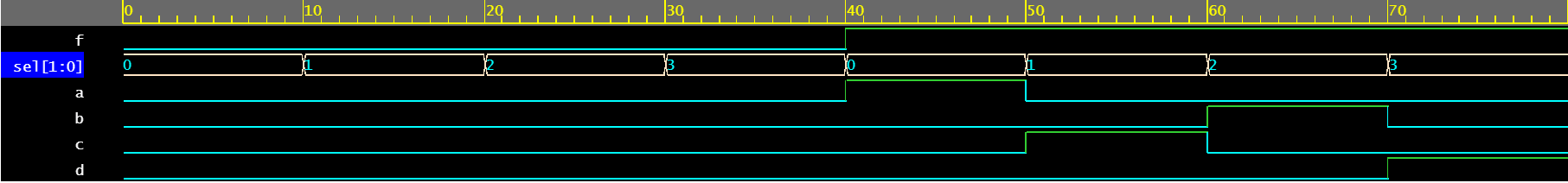
ncsim> run
f=0 sel=0 a=0 b=0 c=0 d=0
f=0 sel=1 a=0 b=0 c=0 d=0
f=0 sel=10 a=0 b=0 c=0 d=0
f=0 sel=11 a=0 b=0 c=0 d=0
f=1 sel=0 a=1 b=0 c=0 d=0
f=1 sel=1 a=0 b=0 c=1 d=0
f=1 sel=10 a=0 b=1 c=0 d=0
f=1 sel=11 a=0 b=0 c=0 d=1
ncsim: *W,RNQUIE: Simulation is complete.
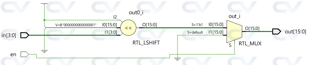
Example #6: 4x16 Decoder
module dec_3x8 ( 	input 			en,
					input 	[3:0] 	in,
					output  reg [15:0] 	out);

  always @ (en or in) begin
    out = en ? 1 << in: 0;
  end

endmodule
Testbench
module tb;
  reg en;
  reg [3:0] in;
  wire [15:0] out;
  integer i;

  dec_3x8 u0 ( .en(en), .in(in), .out(out));

  initial begin
    en <= 0;
    in <= 0;

    $monitor("en=%0b in=0x%0h out=0x%0h", en, in, out);

    for (i = 0; i < 32; i = i + 1) begin
      {en, in} = i;
      #10;
    end
  end
endmodule
ncsim> run
en=0 in=0x0 out=0x0
en=0 in=0x1 out=0x0
en=0 in=0x2 out=0x0
en=0 in=0x3 out=0x0
en=0 in=0x4 out=0x0
en=0 in=0x5 out=0x0
en=0 in=0x6 out=0x0
en=0 in=0x7 out=0x0
en=0 in=0x8 out=0x0
en=0 in=0x9 out=0x0
en=0 in=0xa out=0x0
en=0 in=0xb out=0x0
en=0 in=0xc out=0x0
en=0 in=0xd out=0x0
en=0 in=0xe out=0x0
en=0 in=0xf out=0x0
en=1 in=0x0 out=0x1
en=1 in=0x1 out=0x2
en=1 in=0x2 out=0x4
en=1 in=0x3 out=0x8
en=1 in=0x4 out=0x10
en=1 in=0x5 out=0x20
en=1 in=0x6 out=0x40
en=1 in=0x7 out=0x80
en=1 in=0x8 out=0x100
en=1 in=0x9 out=0x200
en=1 in=0xa out=0x400
en=1 in=0xb out=0x800
en=1 in=0xc out=0x1000
en=1 in=0xd out=0x2000
en=1 in=0xe out=0x4000
en=1 in=0xf out=0x8000
ncsim: *W,RNQUIE: Simulation is complete.

