A SystemVerilog interface allows us to group a number of signals together and represent them as a single port. All these signals can be declared and maintained at a single place and be easily maintained. Signals within an interface are accessed by the interface instance handle.
Syntax
Interface blocks are defined and described within interface and endinterface keywords. It can be instantiated like a module with or without ports.
interface [name] ([port_list]);
	[list_of_signals]
endinterface
Interfaces can also have functions, tasks, variables, and parameters making it more like a class template. It also has the ability to define policies of directional information for different module ports via the modport construct along with testbench synchronization capabilities with clocking blocks. It can also have assertions, coverage recording and other protocol checking elements. Last but not the least, it can also contain initial and always procedures and continuous assign statements.
A module cannot be instantiated in an interface ! But an interface can be instantiated within a module.
SystemVerilog is now popular as a HDL and let's see two cases where an interface is used with the same design in both Verilog and SystemVerilog. To keep things simple in this introductory example, we'll just create a simple interface.
Interface with a Verilog Design
Let us see how an interface can be used in the testbench and connected to a standard Verilog design with a portlist. The code shown below is a design of an up-down counter in Verilog. This module accepts a parameter to decide the width of the counter. It also accepts an input load value load that is loaded into the counter only when load_en is 1.
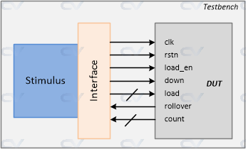
The counter starts counting down when the input down is 1 and otherwise it counts upwards. The rollover output indicates when the counter either transitions from a max_value to 0 or a 0 to max_value.
module counter_ud
  #(parameter WIDTH = 4)
  (
  input 					clk,
  input 					rstn,
  input wire [WIDTH-1:0]	load,
  input 					load_en,
  input 					down,
  output 					rollover,
  output reg [WIDTH-1:0]	count
);

  always @ (posedge clk or negedge rstn) begin
    if (!rstn)
   		count <= 0;
    else
      if (load_en)
        count <= load;
      else begin
      	if (down)
        	count <= count - 1;
      	else
        	count <= count + 1;
      end
  end

  assign rollover = &count;
endmodule
An interface called cnt_if is declared below with a parameterizable value as the width of the counter signal. This task also has a task init() to assign values
interface cnt_if #(parameter WIDTH = 4) (input bit clk);
  logic 			rstn;
  logic 			load_en;
  logic [WIDTH-1:0] load;
  logic [WIDTH-1:0] count;
  logic 			down;
  logic 			rollover;
endinterface

module tb;
  reg clk;

  // TB Clock Generator used to provide the design
  // with a clock -> here half_period = 10ns => 50 MHz
  always #10 clk = ~clk;

  cnt_if 	  cnt_if0 (clk);
  counter_ud  c0 ( 	.clk 		(cnt_if0.clk),
                  	.rstn 		(cnt_if0.rstn),
                  	.load 		(cnt_if0.load),
                  	.load_en 	(cnt_if0.load_en),
                  	.down 		(cnt_if0.down),
                  	.rollover 	(cnt_if0.rollover),
                  	.count 		(cnt_if0.count));

  initial begin
    bit load_en, down;
    bit [3:0] load;

    $monitor("[%0t] down=%0b load_en=%0b load=0x%0h count=0x%0h rollover=%0b",
    	$time, cnt_if0.down, cnt_if0.load_en, cnt_if0.load, cnt_if0.count, cnt_if0.rollover);

    // Initialize testbench variables
    clk <= 0;
    cnt_if0.rstn <= 0;
    cnt_if0.load_en <= 0;
    cnt_if0.load <= 0;
    cnt_if0.down <= 0;

    // Drive design out of reset after 5 clocks
    repeat (5) @(posedge clk);
    cnt_if0.rstn <= 1;

    // Drive stimulus -> repeat 5 times
    for (int i = 0; i < 5; i++) begin

      // Drive inputs after some random delay
      int delay = $urandom_range (1,30);
      #(delay);

      // Randomize input values to be driven
      std::randomize(load, load_en, down);

      // Assign tb values to interface signals
      cnt_if0.load <= load;
      cnt_if0.load_en <= load_en;
      cnt_if0.down <= down;
    end

    // Wait for 5 clocks and finish simulation
    repeat(5) @ (posedge clk);
    $finish;
  end
endmodule
ncsim> run
[0] down=0 load_en=0 load=0x0 count=0x0 rollover=0
[96] down=1 load_en=1 load=0x1 count=0x0 rollover=0
[102] down=0 load_en=0 load=0x9 count=0x0 rollover=0
[108] down=1 load_en=1 load=0x1 count=0x0 rollover=0
[110] down=1 load_en=1 load=0x1 count=0x1 rollover=0
[114] down=1 load_en=0 load=0xc count=0x1 rollover=0
[120] down=1 load_en=0 load=0x7 count=0x1 rollover=0
[130] down=1 load_en=0 load=0x7 count=0x0 rollover=0
[150] down=1 load_en=0 load=0x7 count=0xf rollover=1
[170] down=1 load_en=0 load=0x7 count=0xe rollover=0
[190] down=1 load_en=0 load=0x7 count=0xd rollover=0
Simulation complete via $finish(1) at time 210 NS + 0
Interface with a SystemVerilog design
Let us now see how an interface can be used in the testbench and be connected to a SystemVerilog design module. SystemVerilog allows a module to accept an interface as the portlist instead of individual signals. In the design example shown below, we have substituted the portlist of counter_ud with an interface handle which is used to define design functionality.

`timescale 1ns/1ns

// This module accepts an interface object as the port list
module counter_ud  #(parameter WIDTH = 4) (cnt_if _if);
  always @ (posedge _if.clk or negedge _if.rstn) begin
    if (!_if.rstn)
   		_if.count <= 0;
    else
      if (_if.load_en)
        _if.count <= _if.load;
      else begin
        if (_if.down)
        	_if.count <= _if.count - 1;
      	else
        	_if.count <= _if.count + 1;
      end
  end

  assign _if.rollover = &_if.count;
endmodule
The design instance is passed an interface handle called cnt_if and is used to drive inputs to the design from the testbench. The same interface handle can be used to monitor outputs from the design if required.
// Interface definition is the same as before

module tb;
  reg clk;

  // TB Clock Generator used to provide the design
  // with a clock -> here half_period = 10ns => 50 MHz
  always #10 clk = ~clk;

  cnt_if 	  cnt_if0 (clk);

  // Note that here we just have to pass the interface handle
  // to the design instead of connecting each individual signal
  counter_ud  c0 (cnt_if0);

  // Stimulus remains the same as before
ncsim> run
[0] down=0 load_en=0 load=0x0 count=0x0 rollover=0
[96] down=1 load_en=1 load=0x1 count=0x0 rollover=0
[102] down=0 load_en=0 load=0x9 count=0x0 rollover=0
[108] down=1 load_en=1 load=0x1 count=0x0 rollover=0
[110] down=1 load_en=1 load=0x1 count=0x1 rollover=0
[114] down=1 load_en=0 load=0xc count=0x1 rollover=0
[120] down=1 load_en=0 load=0x7 count=0x1 rollover=0
[130] down=1 load_en=0 load=0x7 count=0x0 rollover=0
[150] down=1 load_en=0 load=0x7 count=0xf rollover=1
[170] down=1 load_en=0 load=0x7 count=0xe rollover=0
[190] down=1 load_en=0 load=0x7 count=0xd rollover=0
Simulation complete via $finish(1) at time 210 NS + 0
What makes it different from Verilog ?
Verilog connects between different modules through its module ports. For large designs, this method of connection can become more time consuming and repetitious. Some of these ports may include signals related to bus protocols like AXI/AHB, clock and reset pins, signals to and from RAM/memory and to other peripheral devices.
Using Verilog Ports
This is the traditional way of port connection in Verilog.
	module d_slave ( input  clk,
                            reset,
                            enable,
                            // Many more input signals
                      output gnt,
                             irq,
                             // Many more output signals);
    // Some design functionality
    endmodule

	module d_top ( [top_level_ports] );
	    reg [`NUM_SLAVES-1:0] clk;                  // Assume `NUM_SLAVES is a macro set to 2
	    reg [`NUM_SLAVES-1:0] tb_reset;
	    // Other declarations

		d_slave slave_0  (  .clk   (d_clk[0]),      // These connections have to be
		                  	.reset (d_reset[0]) 	// repeated for all other slave instances
		                  		...
		                  	.gnt (d_gnt[0]),
		                  	... );

		d_slave slave_1  ( ... );
		d_slave slave_2  ( ... );
	endmodule
Let us consider a scenario where there are twelve slaves in the design shown above. If there is a change made at the d_slave module ports, then the change has to be reflected in all the twelve slave instance connections in d_top as well.
Disadvantages
Some cons of using Verilog port method for connection are :
- Tedious to trace, debug and maintain
- Too easy to make or break design functionality
- Changes in design requirements may require modifications in multiple modules
- Duplication needed in multiple modules, communication protocols, and other places
Using SystemVerilog Interface
Note that the module d_top simply uses the interface to connect with the slave instances instead of repetitively declaring connection to each signal of the slave block as shown before.
interface slave_if (input logic clk, reset);
	reg clk;
	reg reset;
	reg enable;

	reg gnt;
	// Declarations for other signals follow
endinterface

module d_slave (slave_if s_if);

	// Design functionality
	always (s_if.enable & s_if.gnt) begin 	// interface signals are accessed by the handle "s_if"
		// Some behavior
	end
endmodule

module d_top (input clk, reset);
	// Create an instance of the slave interface
	slave_if 	slave_if_inst ( .clk (clk),
	                            .reset (reset));

	d_slave 	slave_0 (.s_if (slave_if_inst));
	d_slave 	slave_1 (.s_if (slave_if_inst));
	d_slave 	slave_2 (.s_if (slave_if_inst));
endmodule
Now, if there is a change to one of the signals in the slave interface, it is automatically applied to all the instances. In SystemVerilog, the module portlist can also have a port with an interface type instead of the usual input, output and inout.
Interface Array
In the example below an interface named myInterface with an empty port list is created and instantiated within the top level testbench module. It is also fine to omit the parenthesis for an empty port list and instead truncate the statement with a semicolon
	// interface myInterface;

	interface myInterface ();
		reg 		gnt;
		reg 		ack;
		reg [7:0]	irq;

		...
	endinterface

	module tb;
		// Single interface handle
		myInterface 	if0 ();

		// An array of interfaces
		myInterface 	wb_if [3:0] ();

		// Rest of the testbench
	endmodule
A single interface called if0 can be instantiated and signals within this interface should be accessed by referencing this handle. This can then be used to drive and sample signals going to the DUT.
We can also have an array of interfaces. Here this array is referred by the name wb_if which has 4 instances of the interface.
	module myDesign ( myInterface dut_if,
	                  input logic clk);

		always @(posedge clk)
			if (dut_if.ack)
				dut_if.gnt <= 1;

	endmodule

	module tb;
		reg clk;

		// Single interface handle connection
		myInterface  if0;
		myDesign 	 top (if0, clk);

		// Or connect by name
		// myDesign  top (.dut_if(if0), .clk(clk));

		// Multiple design instances connected to the appropriate
		// interface handle
		myDesign 	md0 (wb_if[0], clk);
		myDesign 	md1 (wb_if[1], clk);
		myDesign 	md2 (wb_if[2], clk);
		myDesign 	md3 (wb_if[3], clk);

	endmodule
When an interface is referenced as a port, the variables and nets in it are assumed to have ref and inout access respectively. If same identifiers are used as interface instance name and port name in the design, then implicit port connections can also be used.
	module tb;
		reg clk;

		myInterface 	dut_if();

		// Can use implicit port connection when all port signals have same name
		myDesign 		top (.*);

	endmodule
 Note ! An error will occur if an interface without ports is defined without parentheses ().
// Declare an interface without ports
interface mif;
  logic m_a;
endinterface

module tb;
  mif   m_if;      // ERROR !
  mif   m_if();    // Okay
endmodule
  mif 	m_if;
      	   |
xmvlog: *E,NOIPRT (testbench.sv,12|10): Unrecognized declaration 'm_if' could be an unsupported keyword, a spelling mistake or missing instance port list '()' [SystemVerilog].
When values need to be assigned between two different data type variables, ordinary assignment might not be valid and instead a system task called $cast should be used.
$cast can be called as either a task or a function, the difference being that when used as a function, it returns a 1 if the cast is legal. It becomes useful in handling invalid assignments.
Click here for an example !
Syntax
	function int $cast (targ_var, source_exp);

	task $cast (targ_var, source_exp);
Here, targ_var is the target variable and source_exp is the source expression that should be evaluated and assigned to the target variable.
Calling as a task/function
When $cast is called as a task, it will attempt to assign the source expression to the target variable and if it's invalid, a runtime error will occur and the target variable will remain unchanged.
When $cast is called as a function, it will attempt to assign the source expression to the target variable and return 1 if it succeeds. It does not make the assignment if it fails and returns 0. Note that in this case there will be no runtime error, and the simulation will proceed with the unchanged value of the destination variable.
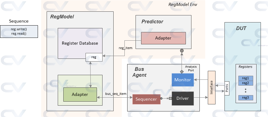
In Register Model, we have seen how to create a model that represents actual registers in a design. Now we'll look at the different components in a register environment required to perform register accesses such as read and write operations.
There are essentially four components required for a register environment :
- A register model based on UVM classes that accurately reflect values of the design registers
- An agent to drive actual bus transactions to the design based on some protocol
- An adapter to convert the read and write statements from the model to protocol based bus transactions
- A predictor to understand bus activity and update the register model to match the design contents
Now let's take a look at some of the common ways of writing constraint expressions inside a constraint block.
Simple expressions
Note that there can be only one relational operator < <= > >= in an expression.
	class MyClass;
		rand bit [7:0] min, typ, max;

		// Valid expression
		constraint my_range { 0 < min;
		                      typ < max;
		                      typ > min;
		                      max < 128; }

		// Use of multiple operators in a single expression is not allowed
		constraint my_error { 0 < min < typ < max < 128; }

		// This will set min to 16 and randomize all others
		constraint my_min {  min == 16; }

		// This will set max to a random value greater than or equal to 64
		constraint my_max {  max >= 64; }
	endclass
Constraint blocks are class members just like variables, functions and tasks. They have unique names within a class. These blocks of expressions are typically used to limit the values of random variables within certain values as specified within the constraint block.
Syntax
	constraint  [name_of_constraint] {  [expression 1];
	                                    [expression N]; }
Expressions listed within the curly braces specify the conditions a solver has to take into account when assigning random values for the variables. It is not necessary to have a single constraint for every variable nor is it required to restrict a constraint block to have conditions pertaining only to a single variable. However you cannot have conflicting constraints spread out in multiple blocks, unless they are turned off using constraint_mode() method which we will see in Disable Constraints.
