Net Types
In Verilog, net types are used to model physical connections between components in digital circuits. They do not store values, its value is determined by the values of its drivers and the default value of a net is typically 'z' (high impedance) when left unconnected.
| Net Type | Description |
|---|---|
| wire | Connects elements with continuous assignment |
| tri | Connects elements with multiple drivers |
| wor | Creates wired OR configurations |
| wand | Creates wired AND configurations |
| trior | Creates wired OR configurations with multiple drivers |
| triand | Creates wired AND configurations with multiple drivers |
| tri0 | Models nets with resistive pulldown devices |
| tri1 | Models nets with resistive pullup devices |
| trireg | Stores a value and is used to model charge storage nodes |
| uwire | Models nets that can should be driven only by a single driver |
| supply0 | Models power supply with a low level of strength |
| supply1 | Models power supply with a high level of strength |
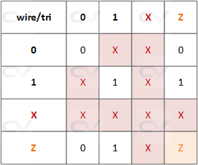
Wire and tri nets
Wire and tri are two types of nets in Verilog that serve as connections between elements in a digital circuit model. While they are functionally identical and share the same syntax, they are given different names to help designers convey the intended purpose of the net within the model.
Wire nets:
- Typically used for connections driven by a single source
- Ideal for representing nets controlled by one gate or one continuous assignment
- The name "wire" suggests a simple, unidirectional connection
Tri (short for tristate) nets:
- Commonly used for nets that may have multiple drivers
- Suitable for modeling buses or other shared connections where different components might drive the net at different times
- The name
triimplies the possibility of multiple drivers and the potential use of high-impedance states
When multiple drivers of the same strength drive conflicting values on a wire or tri net in Verilog, the result is indeed an unknown (x) value.
Wired Nets
Wired nets are of type wor, wand, trior and triand and are used to model wired logic configurations.
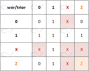
The wor and trior nets are designed to implement wired OR configurations, ensuring that the net's value becomes 1 whenever any of the drivers outputs a 1.
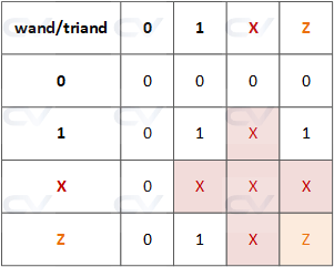
The wand and triand nets are designed to implement wired AND configurations, ensuring that the net's value becomes 0 whenever any of the drivers outputs a 0.
The simulation shown below illustrates how these net types are different compared to a normal wire when there are multiple drivers on the same net.
module tb;
  wor  		wor_net;
  wand 		wand_net;
  trior 	trior_net;
  triand 	triand_net;

  wire      normal_net;

  reg 		driver_1;
  reg 		driver_2;
  reg [3:0] values;

  assign wor_net = driver_1;
  assign wor_net = driver_2;

  assign trior_net = driver_1;
  assign trior_net = driver_2;

  assign wand_net = driver_1;
  assign wand_net = driver_2;

  assign triand_net = driver_1;
  assign triand_net = driver_2;

  assign normal_net = driver_1;
  assign normal_net = driver_2;

  initial
    $monitor("[%0t] driver_1=%0b driver_2=%0b normal=%0b wor=%0b wand=%0b trior=%0b triand=%0b", $time, driver_1, driver_2, normal_net, wor_net, wand_net, trior_net, triand_net);

  initial begin
    values = {1'bZ, 1'bX, 1'b1, 1'b0};

    for (integer i = 0; i < 4; i+=1) begin
      for (integer j = 0; j < 4; j+=1) begin

      	driver_1 = values[i];
        driver_2 = values[j];
      	#10;
      end
    end
  end

endmodule
Observe that a standard net resulted in an X value, while the other net types displayed either 0 or 1.
xcelium> run
[0] driver_1=0 driver_2=0 normal=0 wor=0 wand=0 trior=0 triand=0
[10] driver_1=0 driver_2=1 normal=x wor=1 wand=0 trior=1 triand=0
[20] driver_1=0 driver_2=x normal=x wor=x wand=0 trior=x triand=0
[30] driver_1=0 driver_2=z normal=0 wor=0 wand=0 trior=0 triand=0
[40] driver_1=1 driver_2=0 normal=x wor=1 wand=0 trior=1 triand=0
[50] driver_1=1 driver_2=1 normal=1 wor=1 wand=1 trior=1 triand=1
[60] driver_1=1 driver_2=x normal=x wor=1 wand=x trior=1 triand=x
[70] driver_1=1 driver_2=z normal=1 wor=1 wand=1 trior=1 triand=1
[80] driver_1=x driver_2=0 normal=x wor=x wand=0 trior=x triand=0
[90] driver_1=x driver_2=1 normal=x wor=1 wand=x trior=1 triand=x
[100] driver_1=x driver_2=x normal=x wor=x wand=x trior=x triand=x
[110] driver_1=x driver_2=z normal=x wor=x wand=x trior=x triand=x
[120] driver_1=z driver_2=0 normal=0 wor=0 wand=0 trior=0 triand=0
[130] driver_1=z driver_2=1 normal=1 wor=1 wand=1 trior=1 triand=1
[140] driver_1=z driver_2=x normal=x wor=x wand=x trior=x triand=x
[150] driver_1=z driver_2=z normal=z wor=z wand=z trior=z triand=z
xmsim: *W,RNQUIE: Simulation is complete.
trireg Net
The trireg net in Verilog is a special type of net that is used to model charge storage nodes. Unlike standard nets that do not store values, a trireg net can hold its last driven value when no drivers are active. This makes it suitable for modeling storage elements like capacitors.
A trireg net can be in one of two states:
- Driven State: When at least one driver outputs a value (either 0, 1, or x), the trireg net takes on that value.
- Capacitive State: When all drivers are in a high-impedance state (z), the trireg retains its last driven value.
The strength of the value held by a trireg net in the capacitive state can be specified as small, medium, or medium. This strength is determined at the time of declaration.
tri0 and tri1 Nets
tri0 and tri1 are specialized net types used to model nets with specific pull strengths.
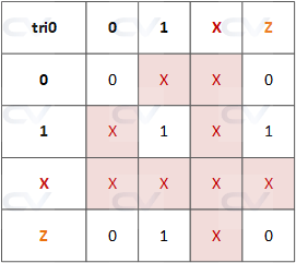
The tri0 net is equivalent to a wire net that has a continuous resistive pulldown device connected to it. When no driver is connected to a tri0 net, its value is 0, reflecting the continuous pull-down effect. If any driver outputs a 1, the value of the tri0 net will be 1, but if all drivers are inactive or in high-impedance state (z), it will hold at 0.
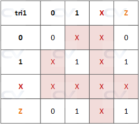
The tri1 net is similar to a wire net but includes a continuous resistive pullup device. When no driver is connected to a tri1 net, its value is 1 due to the pull-up effect. If any driver outputs a 0, the value of the tri1 net will change to 0, but if all drivers are inactive or in high-impedance state (z), it will remain at 1.
The simulation shown below illustrates how these net types are different compared to a normal wire when there are multiple drivers on the same net.
module tb;
  tri0 		tri0_net;
  tri1 		tri1_net;

  wire      normal_net;

  reg 		driver_1;
  reg 		driver_2;
  reg [3:0] values;

  assign tri0_net = driver_1;
  assign tri0_net = driver_2;

  assign tri1_net = driver_1;
  assign tri1_net = driver_2;

  assign normal_net = driver_1;
  assign normal_net = driver_2;

  initial
    $monitor("[%0t] driver_1=%0b driver_2=%0b normal=%0b tri0=%0b tri1=%0b", $time, driver_1, driver_2, normal_net, tri0_net, tri1_net);

  initial begin
    values = {1'bZ, 1'bX, 1'b1, 1'b0};

    for (integer i = 0; i < 4; i+=1) begin
      for (integer j = 0; j < 4; j+=1) begin

      	driver_1 = values[i];
        driver_2 = values[j];
      	#10;
      end
    end
  end
endmodule
xcelium> run
[0] driver_1=0 driver_2=0 normal=0 tri0=0 tri1=0
[10] driver_1=0 driver_2=1 normal=x tri0=x tri1=x
[20] driver_1=0 driver_2=x normal=x tri0=x tri1=x
[30] driver_1=0 driver_2=z normal=0 tri0=0 tri1=0
[40] driver_1=1 driver_2=0 normal=x tri0=x tri1=x
[50] driver_1=1 driver_2=1 normal=1 tri0=1 tri1=1
[60] driver_1=1 driver_2=x normal=x tri0=x tri1=x
[70] driver_1=1 driver_2=z normal=1 tri0=1 tri1=1
[80] driver_1=x driver_2=0 normal=x tri0=x tri1=x
[90] driver_1=x driver_2=1 normal=x tri0=x tri1=x
[100] driver_1=x driver_2=x normal=x tri0=x tri1=x
[110] driver_1=x driver_2=z normal=x tri0=x tri1=x
[120] driver_1=z driver_2=0 normal=0 tri0=0 tri1=0
[130] driver_1=z driver_2=1 normal=1 tri0=1 tri1=1
[140] driver_1=z driver_2=x normal=x tri0=x tri1=x
[150] driver_1=z driver_2=z normal=z tri0=0 tri1=1
xmsim: *W,RNQUIE: Simulation is complete.
Unresolved Nets
A uwire net is an unresolved or unidriver wire used to model nets that allow only a single driver. If more than one driver attempts to drive a uwire, it results in a compile-time error. This restriction helps prevent contention and ambiguity in signal assignment.
Supply Nets
The supply0 and supply1 nets can be used to model the power supplies in a circuit. These nets shall have supply strengths.
